30
4.2
DACS4 CONNECTIONS AND USE
•
Audio Connections
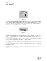
On the front panel of the EVP-1 are two RCA connectors labeled “RIGHT OUT” and “LEFT OUT”. Using the stereo
25' RCA cable provided, connect these outputs to the “AUX” input of the surround processor.
•
Other Connections
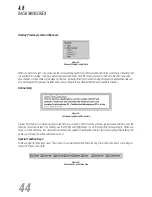
A DB25 cable goes from the LPT1 output of the computer to the mating input connector labeled “COMPUTER” on the
back panel of the EVP.
Connect the 25' DB9 cable provided from the COM1 port on the back of the computer to the DB9 communications
port found on the back panel of the SDEC.
Now connect one end of the special 25’ cable provided between the DB9 connector on the rear panel of the EVP-1
labeled “MIC. BOX” and the round multi-pin connector found on the side of the SMM-5. Microphone connections will
be covered in detail in the “Microphone Connection and Placement” section of this manual.
Many of these connectors have security hardware which, when used, ensures trouble-free operation. Please resist the
temptation to attach the connectors without their security hardware. Although this will save you about two minutes during
setup, all too often the result is a crashed system or intermittent behavior, which results in a substantial loss of time. Keep
in mind that these connectors are subjected to far more insertions than normal. This accelerates wear, loosening the con-
nector pin springs. These connectors are far more likely to fall out from the weight of the cable than it may appear.
•
Microphone Connection and Placement
The DACS4 calibration kit includes five instrumentation microphones. Each microphone is placed on a telescoping
stand. The microphone cables are terminated with an Industry-standard male XLR connector. The barrel of the connec-
tor has a slot shaped cutout on one side, near the edge of the barrel. When the slot is facing up, you have the correct
orientation for insertion into the SMM-5. The mating jacks on the SMM-5 have a spring-loaded retainer key. When
you insert each microphone, you will hear and feel a click when the connection is complete. The retainer key prevents
accidental disconnection. To disconnect a microphone, you must press the key and pull the plug simultaneously.
In the event one or more of the microphones is placed beyond the reach of the cable, you can use the 2-meter
extension cables provided in the kit. Any standard four conductor XLR extension cable can be used for this purpose,
if necessary. It is recommended that the total length not exceed 9 meters.
Room Placement
The SMM-5 is connected to and controlled by the EVP. When you perform a measurement, a discreet data block
is gathered from each microphone. These data blocks are then spatially averaged to create a single data block.
To ensure accurate measurements, it is vitally important that the microphones be placed optimally within the
listening area. See Figure 9 for basic placement guidelines.
Summary of Contents for SYNTHESIS SDEC-1000
Page 1: ...SYNTHESIS SDEC 1000 2500 INSTALLATION GUIDE...
Page 2: ......


