background image

149 


19.4


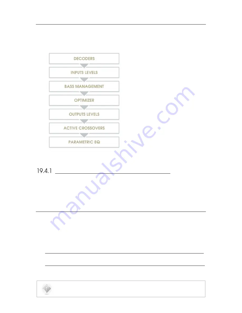
SIGNAL FLOW OF THE SDP-75 


Not shown: 


Input & output routing / Physical inputs & 

outputs 


Manual input & output Eqs 


SETUP PROCESS AND FILTERS CALCULATION 

Active-Crossovers are set up first following a semi-automatic calibration procedure. 

The Optimizer’s filters calculation is made from the speaker measurement. 

Bass  management  crossover  filters  are  applied  after  and  regardless  of  the  loudspeaker  calibration.  The  crossover 

frequencies and bass management mode can therefore be modified after calibration. 

19.5


3D 

SPEAKER 

PLACEMENT 

RECOMMENDATIONS 

For detailed information about speaker placement recommendations, please refer to the following documents: 


Auro-3D Home Theatre Setup Installation Guidelines, available from Auro Technologies. 


http://www.auro-3d.com/wp-content/uploads/documents/Auro-3D-Home-Theater-Setup-Guidelines_lores.pdf 


Dolby Atmos Home Theatre Installation Guidelines, available from Dolby:  


http://www.dolby.com/us/en/technologies/dolby-atmos/dolby-atmos-home-theater-installation-guidelines.pdf 


NOTE: 

As of July 2016, the DTS X Home Theatre Installation Guidelines are not yet available.  

Summary of Contents for SDP-75

Page 1: ...v 4 0 SDP 75 3D SURROUND PROCESSOR USER MANUAL...

Page 2: ...1...

Page 3: ...2 SDP 75 USER GUIDE Software version v4 0 Last update August 2 2017...

Page 4: ......

Page 5: ...nd the Double D symbol are trademarks of Dolby Laboratories For DTS patents see http patents dts com Manufactured under license from DTS Licensing Limited DTS the Symbol DTS in combination with the Sy...

Page 6: ...ground for any purpose The main AC has to be protected by a circuit breaker conforming to local standards Before connecting the equipment check that the main power supply voltage rating corresponds w...

Page 7: ...ONNECTING TO THE SDP 75 29 Overview of the network connection procedure 29 Step 1 download and install a VNC client on your device 30 Step 2 put the SDP 75 and your device on the same network 31 Step...

Page 8: ...66 5 7 SET A MAXIMUM VOLUME 67 5 8 SET THE DIM LEVEL 68 5 9 BACKUP RESTORE OF PRESETS 68 6 OVERVIEW OF THE SETUP PROCEDURE 70 7 ESSENTIAL TOOLS AND SETTINGS 71 7 1 AUDIO CLOCK SETTINGS 71 Audio clock...

Page 9: ...oint 108 12 CALIBRATE THE ACTIVE CROSSOVERS OPTIONAL 110 12 1 OVERVIEW OF THE CROSSOVER SETUP PROCEDURE 110 12 2 CONFIGURE THE ADVANCED SETTINGS OPTIONAL 111 12 3 ADJUST THE MASTER OUTPUT LEVEL 113 12...

Page 10: ...imize according to L R speakers settings 143 FIR and IIR settings 143 Level alignment settings 144 Subwoofer low pass filter settings 144 Decimation settings Advanced FIR settings 144 Advanced FIR set...

Page 11: ...as a future resistant on line update capability that no DSP based system can match 64 bit floating point calculations and 24 bit 192kHz native processing assures the highest sound quality from virtua...

Page 12: ...on about the software tools and settings you need to know before starting the setup process Specify the Speaker Layout How to provide the SDP 75 with all the information about your set of speakers Thi...

Page 13: ...12 July 2016 Software version 4 0 10 First Production Release April 2017 4 1 x IMPORTANT NOTE The content of this document is subject to change without notice...

Page 14: ...X including their respective up mixers HD Audio Codecs Dolby TrueHD DTS HD Master Audio HDMI 1 4a compliant digital audio with 4K and 3D video pass through HDCP 2 2 HDMI input 1 HDMI output 2 UPnP DL...

Page 15: ...n 1 3 JBL SYNTHESIS CERTIFIED INSTALLERS The JBL SDP 75 surround processor provides an unprecedented degree of flexibility and automation along with decoding of every current format and very flexible...

Page 16: ...15 1 4 UNPACKING THE SDP 75 You will find in the SDP 75 packaging The SDP Synthesis SDP 75 Surround Processor Remote Control Power Cord Wi Fi Antenna CR032 Battery SDP 75 Quick Guide Rack Ears...

Page 17: ...ANEL DISPLAY Select Button Source Item Selection Knob Volume Knob Mute Button Power Switch Back Button Menu Button Alignment Status Output Meters Audio Sync Status Output Level Current Source Audio Fo...

Page 18: ...one Input unused 2x Stereo Inputs on XLR 1x 7 1 Input on RCA 3x Stereo Inputs on RCA 8 DIGITAL OUTPUTS 1x AES3 8 or 16 channels on DB25 1x Stereo AES EBU on XLR 1x Stereo S PDIF on RCA 1x Stereo S PDI...

Page 19: ...rmat playback mode selection PRESETS Preset selection MENU BACK ARROWS Navigation in the front panel menu LIGHT Switches off the backlight on the front panel VOL Volume control 1dB step DIM Decreases...

Page 20: ...full user interface in order to operate and or setup the SDP 75 Remotely with an internet browser with a limited access to the user interface allowing to operate the SDP 75 but without all the setup m...

Page 21: ...net menu by connecting a monitor and a mouse to the back panel Go to the Network page of the graphical user interface If you are already connected to the SDP 75 with a VNC Client you can easily check...

Page 22: ...ptimization Settings Opens the lateral Play menu used for daily operation level adjustment source selection and general information See the chapter Daily Operations Opens the Speakers Room setup tool...

Page 23: ...the Sources panel 3 Perform a daily operation such as selecting a different source A detailed description of this interface is provided in the following pages THE LATERAL MENU BAR You can access the P...

Page 24: ...put level added in 1dB steps Mute cuts all outputs Dim attenuates the output level by 20dB Displays which audio source is currently selected as you move the cursor over the icon Source Information Dis...

Page 25: ...75 IN sources SRC the name of the current audio source FMT the audio format UP MIX The up mix format OUT channels EQ the current user EQ OUT the current audio output OPT displays the current status of...

Page 26: ...ol is a highly practical tool used to setup your system It is explained in the Specify the Speaker Configuration chapter Figure 4 The Speakers Room setup tool THE FINE TUNING PANEL The Fine Tuning pan...

Page 27: ...CT INFORMATION Product Information can be displayed on the Graphical User Interface default startup page and or on the front panel menu of the SDP 75 Figure 6 Product information page Version software...

Page 28: ...l About page SOFTWARE UPDATES The SDP 75 was designed to maintain its leadership over time and will therefore benefit from continuous updates as well as new features Software updates and support can b...

Page 29: ...l installation if needed change the network configuration to meet the requirements to integrate the SDP 75 into your overall home theater system For the final installation of the system we suggest to...

Page 30: ...hese options A Your device joins the SDP 75 s Wi Fi network Disconnect your device from your usual Wi Fi network and connect it to the SDP 75 s own Wi Fi network Access Point B The SDP 75 joins your e...

Page 31: ...OS X computer running OS X version 10 5 or higher you can choose to use Apple s Screen Sharing VNC client integrated into the OS X operating system In this case you don t need to download an addition...

Page 32: ...work named SDP XX where XX is the serial number of your SDP 75 Enter the following password calibration Use the SDP 75 front panel to check its network status go to the Setup Network menu to see its I...

Page 33: ...ings page Go to Settings and click on the Wi Fi menu item located in the top left side of the page In the Chose a network list click on the network SDP XX where XX is the serial number of your SDP 75...

Page 34: ...thout switching back and forth between two different Wi Fi networks To connect the SDP 75 to an existing Wi Fi network you need to use the front panel menus to change the Wi Fi settings 1 Click on the...

Page 35: ...nt panel to check that it now has an IP address go to the Setup Network menu to see the network configuration Once the SDP 75 is connected to your local network you can move to the next step of the pr...

Page 36: ...on SDP XX where XX is the number of the SDP 75 Figure 18 selecting the VNC Server SDP XX The field VNC server address now shows the name VNC Server on SDP XX where XX is the number of the SDP 75 Go to...

Page 37: ...This will display the following window 4 Click on the Share Screen button This will display the Screen Sharing login panel 5 Enter the password which is the six digit serial number of your SDP 75 a t...

Page 38: ...of the VNC Login window 3 The Host s IP address is automatically filled You only need to enter the password which is the six digit serial number of your SDP 75 the password is 00000X if the number of...

Page 39: ...r SDP 75 s VNC Server has 3 digits Etc WRITE DOWN THE IP ADDRESS OF THE SDP 75 If your VNC client is not zeroconf enabled it cannot find the SDP 75 s VNC Server automatically This is the case of the T...

Page 40: ...through the settings Figure 24 IP address in the Setup Network Wi Fi page via the front panel GETTING THE IP ADDRESS FROM THE ETHERNET SETTINGS To get the IP address from the Ethernet settings via th...

Page 41: ...button This will open the VNC Authentication window 4 In the VNC Authentication window enter the password which is the six digit serial number of your SDP 75 printed on the back panel a The password...

Page 42: ...HECKING THE WI FI SETTINGS To check the Wi Fi settings via the front panel 1 Click on the menu button 2 Go to the Setup Network Wifi page 3 Turn the Source Item selection knob to scroll through the se...

Page 43: ...1 Click on the menu button 2 Select the Setup Network Ethernet page 3 Turn the Source Item selection knob to scroll through the settings Figure 28 Setup Network Ethernet page via the front panel CONN...

Page 44: ...the SDP 75 as Wi Fi Access Point AP password indicates the password to be used when attempting to join the SDP 75 s Wi Fi Access Point AP netmask indicates the netmask of the SDP 75 s Wi Fi Access Poi...

Page 45: ...ns the Wi Fi Status Modes page Figure 29 the Setup Network page Click on the Connect button in the bottom right corner of the page This will display the available Wi Fi networks The encryption column...

Page 46: ...ting network wirelessly To change the Wi Fi settings of your SDP 75 via the graphical user interface 1 Open the Advanced Settings interface 2 Go to the Setup Network page 3 Press the Setup button to d...

Page 47: ...required to remotely switch the SDP 75 on with a Wake on Lan command IP address indicates the IP address of the Ethernet interface of the SDP 75 Netmask indicates the netmask of the local area networ...

Page 48: ...that the router runs a DHCP server This is the case in most domestic environments To configure the Ethernet connection manually select the Manually specify Network parameters option and hit the Apply...

Page 49: ...OUT ZERO CONFIGURATION NETWORKING Zero configuration networking zeroconf is a networking technology that makes it easy to set up and use devices and services on a network Because zeroconf enabled devi...

Page 50: ...the server supports these formats the SDP 75 can decode and play high resolution 24 bit 192 kHz WAV AIFF FLAC and 16 bit 192 kHz OGG music files 3 2 UPNP NETWORK ARCHITECTURE This architecture repres...

Page 51: ...qualified based on the following requirements JRiver MediaCenter PS Audio eLyric Music Manager These software has been selected tested and qualified based on the following requirements UPnP server and...

Page 52: ...iver Media Center is a commercial software available for PC and Mac DOWNLOAD www jriver com download html PS Audio eLyric Music Manager www psaudio com eLyric Music Manager is a free alternative media...

Page 53: ...m your tablet or your computer connected to the same network as the SDP 75 o with a VNC Client connected to the SDP 75 s VNC Server o with a web browser accessing the SDP 75 s web based interface With...

Page 54: ...and takes about 60 seconds to complete its start up While the system starts the front panel screen displays the following image Figure 35 Front panel startup image To shut the SDP 75 down press the f...

Page 55: ...t button Use one of the direct selection buttons to choose among the first four sources also available on the remote control NOTE With factory settings the last used source is recalled on start up PRE...

Page 56: ...the SDP 75 below the Optimizer status The Sampling Rate of the audio being played is indicated on the left side of the front panel display of the SDP 75 The current up mixer used is displayed on the f...

Page 57: ...ll as 2 buttons to browse through the sources LISTENING FORMAT SELECTION These allows you to switch between the different listening format and so between the different Up mixers This can be done on th...

Page 58: ...k button LIGHT BUTTON The Light button allows to turn off the front panel screen s backlight Pressing on another button will temporarily turn on the backlight to let you know the settings you are chan...

Page 59: ...on also allows you to mute all audio outputs of the SDP 75 A Dim button also allows you to decrease the volume by 20dB NOTE By default the last used volume is recalled at start up SOURCE SELECTION Sou...

Page 60: ...cted through the graphical user interface Figure 39 preset selection in the graphical user interface CHECKING THE FORMAT OF INCOMING AUDIO The format of incoming audio is displayed in the lateral menu...

Page 61: ...ible to configure two Source Configurations set on the same inputs but set with different names to recall different settings The Home Source Config page consists of one vertical tab per source on the...

Page 62: ...es For example one Blu ray player one Network player and a Digital TV to switch between different outputs For example a pair of 2 0 channel loudspeakers and a 5 1 home cinema setup to switch between s...

Page 63: ...s Rrs Listening Format Select the default format you want to use with this source The SDP 75 will be forced to decode and up mix if possible in this format o Auto Will automatically up mix in the corr...

Page 64: ...ce as power on default source This can be modified in the Home Sources Config page of the Advanced Settings Interface Default Source Select the vertical tab of the source you want to use as default so...

Page 65: ...Optimizer is off only the manual settings related to the audio processor are applied o Routing as defined in Speaker Configuration Table in the 3D View page of the Main interface o The Active Xovers f...

Page 66: ...f not saved in a preset Please manipulate presets with care since overwriting a preset does not require confirmation The Presets page consists of four vertical tabs Presets 1 9 includes the Built in p...

Page 67: ...be to 1 Reload the preset to recall the exact configuration you want to duplicate 2 Use the Save button of an empty preset to copy it NOTES The Built in preset is locked and cannot be overwritten A sp...

Page 68: ...67 5 7 SET A MAXIMUM VOLUME The Maximum volume can be selected in the Startup option tab of the product information menu Figure 46 the Info Startup page maximum volume...

Page 69: ...ge in the Info menu of the main page Setup tab Here the parameter Dim level dB will define the amount of Dim to apply on the master volume when the Dim is engaged Figure 47 the Info Startup page Dim l...

Page 70: ...stem and a bug report is generated After the restart of the SDP 75 you can save that bug report on the USB Key and send it to JBL Synthesis Support at csupport harman com o Save Screenshots to the USB...

Page 71: ...hat the routing of the speakers is correct 2 Optional if one or more speakers require multi amplification configure calibrate and verify the SDP 75 s intelligent active crossovers 3 Fine tune the spea...

Page 72: ...ystem is not able to produce sound like pink noise or sine waves If this happens to you please set the clock to Master mode or simply switch to an analog input AUDIO CLOCK STATUS INFORMATION The Word...

Page 73: ...ttings page in the Advanced Settings The Setup Clock page includes Status Information the same information provided in the Clock page of the main user interface Clock Mode slave or master modes Clock...

Page 74: ...r Meters page Both the peak levels and the RMS levels are displayed Figure 50 metering inputs and outputs You can visualize the peak level of each channel The highest level registered on each channel...

Page 75: ...nterface from the Processor Inputs page To play a pink noise from the Speakers Room setup tool click on the Pink Noise button of the corresponding output channel Figure 51 playing Pink Noise from the...

Page 76: ...ute and Solo buttons that allow you to mute or solo any input or output channel at any time To Mute Solo an input channel go to the Inputs tab and click on the Mute Solo button of the corresponding in...

Page 77: ...ization on off in the Advanced user interface Optimization On Off buttons the buttons in the Optimizer Settings Runtime page allow the user to selectively enable disable the different corrections appl...

Page 78: ...peakers before and after the Trinnov optimization as well as the correction filters The acoustical graphs are available in the Optimizer Graphs page of the Advanced user interface It is possible to di...

Page 79: ...lculations These graphs only take into account the automatic filters computed according to the Optimizer Settings page not the manual adjustments made in the Processor page The display settings will b...

Page 80: ...on each tab and sub tab Figure 56 Comprehensive acoustical graphs For each level you can order the data through various criteria The speaker L R C Sub The point of measurement in the case of a multip...

Page 81: ...80 Figure 57 Focusing on specific graphs...

Page 82: ...onfigure the settings of each speaker the channel mapping to Dolby DTS Dolby Atmos DTS X and Auro 3D formats and the output routing Verify the routing of the speakers by playing pink noise on each spe...

Page 83: ...ighlighted below Figure 58 The Speaker Room setup tool The Controls box located in the top right corner of the window allows you to navigate through the 3D view You can rotate the view zoom in and zoo...

Page 84: ...media and file based media Below is an example of a specific speaker layout designed to support multiple formats Figure 59 Example of a specific configuration with 16 speakers This configuration of 16...

Page 85: ...o support multiple surround and 3D formats such as Dolby Atmos DTS X and Auro 3D Note that this layout can be modified to support the largest Dolby Atmos configuration The 16 speaker layout Standard 9...

Page 86: ...nd add the missing speakers or select a bigger system and remove the extra ones IMPORTANT NOTE it is critical to distinguish speakers from channels because one speaker may be used to reproduce multipl...

Page 87: ...ant to add Figure 61 Adding a speaker IMPORTANT NOTE Some configurations are not allowed by the decoder specifications In such case a red warning will be displayed on the side panel and the relevant s...

Page 88: ...enable speaker from the 3D view click on one of the Dolby Top Speakers As explained above the Dolby enabled speakers are using the signal from Top speakers to recreate the immersion effect The speaker...

Page 89: ...part of the Speaker Room setup tool allows you to Manually map the channels of the Dolby Dolby Atmos DTS DTS X or Auro 3D formats to each speaker Configure the arrays of speakers for Dolby and DTS le...

Page 90: ...e currently selected speaker is displayed in yellow in the 3D view The available settings for each speaker are the following Dolby Dolby Atmos Auro3D DTS and DTS X channel mapping see below Amplificat...

Page 91: ...vanced Settings user interface Further information about the active crossovers can be found in the Calibrate the Active Crossovers chapter 8 10 MAPPING THE CHANNELS OF DIFFERENT FORMATS The new Immers...

Page 92: ...the routing is correct from the SDP 75 to the speakers In addition to this procedure when a new source is connected to the SDP 75 you should also verify that the routing is correct from the source to...

Page 93: ...your speaker layout will not be lost IMPORTANT NOTE The SDP 75 needs to be synchronized on an audio clock either external Slave mode or internal Master mode in order to produce the pink noise If a Di...

Page 94: ...as to be done within the Speaker Room setup tool using the mapping column of each decoder As explained in the previous chapter Specify a speaker layout Mapping the channels of different formats sectio...

Page 95: ...content Left and Right Wide speakers will play Lss and Rss channel simultaneously with Left and Right surround speakers For DTS Legacy content they will play Lss and Rss channel simultaneously with L...

Page 96: ...our arrays of speakers won t be lost The Selected speakers can all be modified simultaneously using the control panel in the top left corner You can add or decrease gain using 1dB or 1dB buttons or by...

Page 97: ...oders are implemented in the SDP 75 Dolby decoders DTS decoders 3D decoders Dolby Digital Dolby Digital Plus Dolby TrueHD DTS Digital Surround DTS HD High Resolution Audio DTS HD Master Audio Dolby At...

Page 98: ...e incoming content won t be modified and will be played as it is Up mix on Native The incoming content will played using the corresponding up mixer but with the Legacy speaker layout Dolby or DTS colu...

Page 99: ...Layout Used DTS X Native Dolby Atmos Layout Used Atmos Neural X Up mixer Layout Used DTS X Native DTS X Layout Used DTS X Neural X Up mixer Layout Used DTS X Auro 3D Auro 3D Up mixer 1 Layout Used Aur...

Page 100: ...d listening mode Legacy None No Up mix Layout used selected in Decoder General settings None No Up mix Layout Used Dolby Bed Original 7 1 Layout Used Dolby None No Up mix 2 Layout Used DTS Bed Origina...

Page 101: ...3D listening format will play Native Auro 3D content CPU LOAD Do not forget that Up mixers require a lot of CPU resources especially in 96 kHz with high channel count Auro Matic The Auro 3D up mixer d...

Page 102: ...ll using the Select knob and confirm using the Enter button The current listening format is underlined DECODERS CONFIGURATION To configure the Decoders from the front panel press the Menu button Using...

Page 103: ...wn list Figure 68 The surround up mixer option DECODER CONFIGURATION To configure the decoder parameters for the Dolby DTS and Auro 3D decoders 1 Click on the IN sources menu item of the lateral menu...

Page 104: ...on is activated the SDP 75 will automatically switch to the input format of the decoder The SDP 75 virtually replaces the speakers at their ideal position recommended by the curent decoder and provide...

Page 105: ...TrueHD Loudness Management use the loudness management information provided in the incoming signal s metadata o DRC Settings Auto Automatic DRC low level boost and high level cut Enabled Enable the D...

Page 106: ...ormats into stereo Audio description switch on the visual description track intended for the blind and visually impaired Channel remapping This setting is only applicable for surround formats o None N...

Page 107: ...surround speaker layout so that height speakers are disabled Incoming stereo content is up mixed to a surround format and incoming Auro 3D content is down mixed to a surround format o Stereo enforce...

Page 108: ...amplifier active speakers before calibration to avoid dangerous level jumps 11 2 CHECKLIST BEFORE YOU START Please go through the following checklist to make sure you are ready to start the calibratio...

Page 109: ...upports single point and multi point calibrations In both scenarios a reference measurement position should be chosen carefully since it will be used by the Optimizer for Cross over driver alignment L...

Page 110: ...109 Figure 73 Microphone reference position Point the front red LED to the center of the speakers...

Page 111: ...1 OVERVIEW OF THE CROSSOVER SETUP PROCEDURE The overall setup and calibration process of the SDP 75 active crossovers is performed through two different tools Use the Speaker Room Setup Tool to Confi...

Page 112: ...kers displayed depends on the number of loudspeakers specified in the Speaker Room Setup tool Figure 75 advanced crossover settings The following settings are available for each loudspeaker The type o...

Page 113: ...Cancel Changes button to cancel your modifications If change is accepted press the Save button of the preset of your choice in the Presets page to save the changes otherwise changes will be lost The t...

Page 114: ...ate button in the Setup ActiveXovers page of the Advanced Settings interface Adjust output level 1 Increase the master level until the test signal moves to the second driver 2 Use the SDP 75 s meterin...

Page 115: ...delay and polarity of each driver Before calibration please note The calibration procedure has to be done individually for each speaker An MLS signal is sent to each driver of the selected speaker wh...

Page 116: ...page of the Advanced Settings interface Follow the on screen instructions regarding the microphone 12 5 VERIFY THE SOUND OF THE CALIBRATED CROSSOVERS Once the calibration of the active crossovers is f...

Page 117: ...and polarities set previously are ignored during the calibration In other words adjusting these parameters before launching the calibration will have no effect on the result Under some circumstances...

Page 118: ...sten carefully to each speaker connected to the crossover You can play pink noise from the SDP 75 and or play your favorite music cinema samples 12 6 SAVE THE PRESET Last but not least don t forget to...

Page 119: ...Sound Pressure Level for proper calibration Until that minimum SPL is reached the test signal will keep playing through the same speaker For safety matters we recommend to perform that first calibrati...

Page 120: ...hapter Make sure the measurement environment is silent Press the Mute button to cut the outputs this step must ALWAYS be performed before pressing the Calibrate button Press the Calibrate button in th...

Page 121: ...ould be damaged Unstable position for speaker o Someone may have moved during the calibration o Too many strong reflections around the microphone environment could be disturbing the impulse response m...

Page 122: ...The speakers are seen from above Elevation view The speakers are seen from the listening point Relative degrees of elevation and azimuth are displayed Details view A table listing the measured distanc...

Page 123: ...gure 89 top view of a 7 1 4 after calibration This view also provides the RT60 on the top left corner of the page Overlay both representations with the Scale and Ref Radius options to verify the compl...

Page 124: ...4 system after calibration NOTE If one speaker cannot be located during calibration it will be displayed in the center of the circle The Summary page provides additional measurements for each speaker...

Page 125: ...ation is the delay that is added to every speaker to time align the system BM Delay may be added to the subwoofer to improve the crossover with the satellites More rarely if the subwoofer is in advanc...

Page 126: ...n indicates that the Optimizer is ready Computation time varies depending on the number of speakers in the system and on the Optimizer parameters IMPORTANT NOTE Once the speaker system has been calibr...

Page 127: ...e recommended bass management setup procedure is as follows Analyze the acoustical graphs of the speaker measurements in order to understand the low frequency response of each speaker in the room Deci...

Page 128: ...every speaker you can Specify a High Pass Frequency Activate one or more subwoofers that will reproduce the lower frequencies from that channel Setup the gain for each subwoofer Invert the polarity f...

Page 129: ...ass management mode which is recommended for all installations utilizing subwoofers On LFE to LR Distributes the LFE signal to the Left and Right speakers Can be used when there is no subwoofer in the...

Page 130: ...129 Figure 95 Access to the Bass Management options...

Page 131: ...filters The 3 sections are detailed in the sub chapters below The configuration steps are the followings Enter the desired settings in the 1 Set filters table Select the speakers on which you want to...

Page 132: ...on will define the low end cutoff frequency of the signal send to the satellites You can here select the type of filter Linkwitz Riley Bessel or Butterworth the cutoff frequency and the slope use by t...

Page 133: ...the channel will be redirected and played by the subwoofer s You can select the type of filter Linkwitz Riley Bessel or Butterworth the cutoff frequency and the slope used by this filter These setting...

Page 134: ...This first section is here to choose which subwoofer is assigned to the LFE channel A subwoofer assigned to the LFE will play the 1 of the content To assign the LFE channel to a subwoofer please tick...

Page 135: ...hich is typically the case In such multiple subwoofers configurations two typical cases are handled by the SDP 75 If subwoofers are considered as decorrelated away from each other their power add up I...

Page 136: ...roup of speakers Press the Apply Change button 15 2 SETTING UP ONE OR MORE TARGET CURVES To edit the target curve for one or more speakers go to the Optimizer Settings Target Curve page in the Advance...

Page 137: ...ve in the Advanced Settings user interface NOTE By default the Optimizer will use both IIR and FIR filters to achieve the target curve In addition to target curves several other parameters define the...

Page 138: ...e confident that the system is ready to deliver the best home theatre experience available today 16 1 VISUALIZE THE ACOUSTICAL GRAPHS FOR ALL SPEAKERS Go to the Optimizer Graphs page and visualize the...

Page 139: ...rtantly listen carefully to your system by playing your favorite music and cinema samples As an option you could also play pink noise from the SDP 75 to perform additional acoustical measurements with...

Page 140: ...g optimization on off Viewing the acoustical graphs For a detailed explanation of all those tools please refer to the Essential Tools and Settings chapter 17 1 MAIN OPTIMIZATION SETTINGS The Optimizer...

Page 141: ...ed approach See also the Limiter Curve functionality described below Acoustic parameters Quantity of Early Reflections and Resolution of Energy Response The SDP 75 uses two different approaches for th...

Page 142: ...ate editing points around the required frequency range Use the Move point mode and your mouse to edit the limiter curve for the required frequency range Use the Delete point mode to delete editing poi...

Page 143: ...1 3 octave A smaller value such as 1 12 octave can be used to display more details in the frequency response FRONT SURROUND SPEAKER SETTINGS The following features can be separately enabled disabled...

Page 144: ...re not optimized at all Align L R on target Default is On If this setting is on the Optimizer applies filters on the Left Right speakers using their average response as target If this setting is off o...

Page 145: ...llowing options Cutoff frequency Default is disabled Defines the cutoff frequency for the low pass filter that can be applied to the subwoofer Filter type Default is Butterworth Defines the type of fi...

Page 146: ...point Algorithm is able to take every single measurement point into account The purpose of multi point measurement is not only to optimize a wider listening area but also to get more information from...

Page 147: ...nd impact on the quality of the results Figure 105 Relevant multi point measuremen t positions As an example multi point measurements can be performed for a single listening position Figure 106 Releva...

Page 148: ...the points have failed the calibration but you don t want to perform a calibration again The weight can be adjusted after a calibration you don t have to run a complete calibration to take weight chan...

Page 149: ...installer or an experienced IT technician for technical support It can also be switched off remotely over the network using the command provided within our automation protocol for that purpose availa...

Page 150: ...ement mode can therefore be modified after calibration 19 5 3D SPEAKER PLACEMENT RECOMMENDATIONS For detailed information about speaker placement recommendations please refer to the following document...

Page 151: ...quite popular pinout is the one from Yamaha You should check which pinout your equipment is using before connecting it to the SDP 75 Unbalanced connections must connect signal to SubD Hot and shield...

Page 152: ...e room For each loudspeaker the Optimizer gathers the following information full 3D position amplitude response phase response NOTE Another quite popular pinout is the one from Yamaha You should check...

Page 153: ...ers capsules and electronics Camera Microphone thread POWER SUPPLY The power supply located in the base of the microphone uses a standard 9V PP3 LR61 battery The red led indicates the battery Level Re...

Page 154: ...ne If not use the Configure button of the required Measurement to select the correct compensation file For future measurements use the Default Microphone button to make the required compensation file...

Page 155: ...154 CONNECTION ORDER...

Page 156: ...155 Thankyouforyourattention PleaseenjoyyourSound...

Page 157: ...156...

Reviews: