background image

Dolby Pro Logic (Non-Digital) – Line Level

Use this installation method
for Dolby Pro Logic appli-
cations (not Dolby Digital, DTS
or other digital processing),
where the receiver/processor
is equipped with a subwoofer
output, or a volume-controlled
preamp (line-) level output:

Use RCA-type patch cords 
to connect the line-level
subwoofer outputs on your
receiver or amplifier to the
line-level inputs on the
subwoofer. IMPORTANT: Do
not use the LFE input on the
subwoofer with Dolby

Pro Logic processors. Note: If
your receiver or amplifier only
has one subwoofer output
jack, then you will need to use
a Y-connector (not included).
Plug the male end of the Y-
connector into your receiver
or amplifier’s subwoofer
output jack, and connect each
of the two female ends to
separate RCA-type patch
cords. Finally, plug the RCA-
type patch cords into the line-
level inputs on the subwoofer.

Connect each speaker to 
the corresponding speaker
terminals on your receiver 
or amplifier.

Make sure your receiver or
processor is correctly
configured to indicate that the
subwoofer is “On.”

Note for advanced users: If
your receiver/processor has a
built-in low-pass crossover
filter for the subwoofer output,
you may use the LFE input to
bypass the subwoofer’s
internal crossover.

Use this installation method
for Dolby Digital, DTS or other
digital surround processors: 

Use the line-level input jack
marked “LFE” for the Low-
Frequency Effects channel.
Connect this jack to the LFE
output or subwoofer output 
on your receiver or amplifier.
Connect each speaker to the
corresponding speaker

terminals on your receiver 
or amplifier.

Make sure that you have
configured your surround-
sound processor for
“Subwoofer On.” The front
left, front right, center and
rear speakers should all be
set to “Small.”

Dolby Digital or DTS (or Other Digital Surround Mode) Connection

LINE LEVEL IN

LFE INPUT

LFE OUT

L

R

SUBWOOFER

RECEIVER

+       –

+       –

+       –

+       –

+       –

+       –

+       –

+       –

+       –

+       –

Receiver

Subwoofer 

Out

Left

Front

Left

Rear

Right

Front

Right

Rear

Subwoofer

R        L

L

Center

Line-

Level

In

Right Surround

Right Front

Left Surround

Left Front

Center

Summary of Contents for SCS150SI

Page 1: ...Simply Cinema Series SCS150SI Surround Cinema Speakers SERVICE MANUAL JBL Consumer Products 250 Crossways Park Dr Woodbury New York 11797 Rev0 11 2001 ...

Page 2: ... shielded Dimensions H x W x D 8 1 8 x 3 1 2 x 3 7 8 206mm x 89mm x 99mm Weight Center Recommended Power 10 100 watts Impedance 8 ohms nominal Sensitivity 88dB 1 watt 1 meter Tweeter One 1 2 titanium laminate dome video shielded Midrange Dual 3 drivers video shielded Dimensions H x W x D 3 1 2 x 8 1 8 x 3 7 8 89mm x 206mm x 99mm Weight 2 65lb 1 2kg Subwoofer SUB150 Amplifier 150 watts RMS Woofer 1...

Page 3: ...ve n a LFE Low Pass fixed Hz 2dB Slope Q 2nd dB Octave n a Subsonic filter HPF Hz 2dB Slope Q 2nd dB Octave n a Limiter YES n a Features LFE Input YES functional BW Limited to 500 Hz Volume pot Taper lin log log functional ATO YES functional Signal Sensing ATO ATO test Frequency 50 Hz functional ATO Line Level 2 mV functional 2mV 50Hz into Line Input w 1 ch driven ATO Speaker level input 50 mV fuc...

Page 4: ...ubwoofer unscrew the colored collar until the pass through hole in the center post is visible under the collar Insert the bare end of the wire through this hole then screw the collar down until the connection is tight The hole in the center of each collar is intended for use with banana type connectors ...

Page 5: ...t terminals on the subwoofer that are marked High Level In Connect the left and right terminals on the subwoofer that are marked High Level Out to the cor responding terminals on the back of your front left and right speakers Connect your receiver or amplifier s center left and right surround speaker terminals to the corre sponding terminals on the back of your center left and right surround speak...

Page 6: ...terminals on your receiver or amplifier Make sure your receiver or processor is correctly configured to indicate that the subwoofer is On Note for advanced users If your receiver processor has a built in low pass crossover filter for the subwoofer output you may use the LFE input to bypass the subwoofer s internal crossover Use this installation method for Dolby Digital DTS or other digital surrou...

Page 7: ...period of time or if the subwoofer will not be used switch the Master Power switch to the Off position Volume POWER HIGH LEVEL SUBWOOFER LEVEL OUT IN L R LINE LEVEL IN LFE L R AUTO ON MIN MAX SUB 150 AC 120V 60Hz 250 Watts 3 15A 250V TYPE T IMPORTANT CONNECT STRIPEDWIRE TO RED SPEAKER TERMINAL GREEN ON RED STANDBY AVIS RISQUE DE CHOC ÉLECTRIQUE NE PAS OUVRIR WARNING FOR CONTINUED PROTECTION AGAINS...

Page 8: ...er or amplifier and you should consult the owner s manual for that product for further information If the problem has followed the speaker consult your dealer for further assistance or if that is not possible visit our Web site at www jbl com for further information If there is no sound from the center speaker Check all wires and connections between receiver amplifier and speaker Make sure all wir...

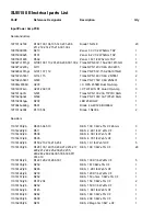
Page 9: ...R SALE SUB150 CABINET 1 2 WI5447 FOOT MAIN PLASTIC BODY 4 3 WI5448 FOOT RUBBER BOTTOM 4 4 06 T43005 FOOT SCREW T4 30L 4 5 25MF12DZB DW02 10 WOOFER 1 6 06 T4205012 AMPLIFIER WOOFER SCREWS T4 20L 15 7 NOT FOR SALE SUB150 AMPLIFIER 1 ...

Page 10: ......

Page 11: ......

Page 12: ......

Page 13: ......

Page 14: ......

Page 15: ......

Page 16: ...8 Wall bracket for sats wi0409 Support mural for sats CENTER CHANNEL SCS150SI CENTER 1 Complete Center Channel xr5138 1 Crossover network wi5213 g Foot xc035007 Metal Grille PACKING ai0193 Reply card ai5139 Owner s Manual wg5270 Outer carton at5160 Warranty card sal063 1 Wire set 20 center sal5009 Wire set 40 surround sal5019 Wire set 15 front satellites wp5187 Packing Foam ...

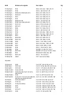
Page 17: ...92162tip32c Q502 Trans PNP 100V 3A TIP32C SGS 1 19510204hgw D209 LED 204HGW 1 19700kbu606g D501 Diode 4A 400V KBU606G 1 197101n4004 D110 504 Diode 1N4004 2 Resistors 11014103j26 R503 504 510 RES 10K 1 4W 5 CF 26mm 3 11014222j26 R511 RES 2 2K 1 4W 5 CF 1 11014432j26 R506 RES 4 3K 1 4W 5 CF 1 11014472j26 R505 RES 4 7K 1 4W 5 CF 1 11016102j26 R153 213 214 215 254 RES 1K 1 6W 5 CF 5 11016103j26 R128 1...

Page 18: ... 116162202f26 R318 RES 22 0K 1 6W 1 MF 1 11020332jk3 R134 RES 3 3K 2W 5 7 5mm 1 11120102jk3 R148 RES MF 1K 2W 5 7 5mm 1 11130471jk2 R501 502 RES MF 470 ohms 3W 5 10mm 2 11350s68j00 R147 RES CEW 0 068 ohms 5W 1 11012472j00 R201 202 RES 4 7K 1 2W 5 2 115h503a102 VR201 POT Gain control 50K 1 Capacitors 132103kb00 C500 CAP MY 0 01uF 200V 10 1 1385478m63 C501 502 CAP E 4700u 63v 20 pitch 10mm 2 129a154...

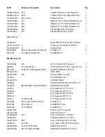
Page 19: ... 13 16 RES 2 20K 1206 5 3 11812062701j R10 RES 2 70K 1206 5 1 11812063000j R24 RES 300 0 ohms 1206 5 1 11812063301j R14 15 27 28 RES 3 30K 1206 5 4 11812063902j R3 RES 39 0K 1206 5 1 11812064700j R8 RES 470 ohms 1206 5 1 11812064701j R1 5 12 RES 4 70K 1206 5 3 11812064702j R17 RES 47 0K 1206 5 1 11812064704j R4 RES 4 70M 1206 5 1 118120647r0j R20 21 RES 47 0 ohms 1206 5 2 141c0101k50 C4 CAP CA 100...

Page 20: ...L TYPE t 1 6mm S P C C 2 652m3t03 TO ID150 PCB 104qsub150d0 SOLDER TERMINAL M3 t 0 3 1 653hsqlc1004 HEAT SINK 1 162a040d001 M10 2Pin spk Wires conn Asy 1 176wjce1 U L TERMINAL CE 1 1 640rpsub150 AI REAR PANEL 1 700kb800 PLASTIC KNOB 46077 W SOFT P V C 1 707ac800 REAR PANEL 1 REAR COVER 1 BUSHING 4K 4 NO BB 2 723a125 EVA Gasket 213 15 2 0mm 2 723a125 1 EVA Gasket 213 15 1 0t 2 723b125 EVA Gasket 23...

Page 21: ...RCA JK RCB 202V D G GOLD PLATE A W 1 17420810360g JK203 SPK JK BP 8PIN SH0810360G 1 1751c07v01 M201 Wafer 7PIN PITCH 2 5mm 1 1751d02v01 M100 Wafer 2PIN PITCH 3 96mm 1 1751d03v01 M500 Wafer 3PIN PITCH 3 96mm JST VH 1 180pbr12c11s SW501 Power Switch BR12C11S 1 180tms7210v SW201 SWITCH SLIDE 6PIN MS7210V 1 193201815t2 For Q10 11 CERAMIC ISOLATOR 2 1201000003 FB1 2 Ferrite BEA 10W AI YT C3104 0051 2 ...

Page 22: ......

Page 23: ......

Page 24: ......

Reviews: