background image

OPERATION

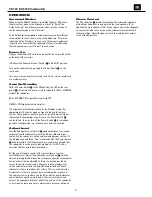
Surround Modes

When using the CS6100 speakers in a Dolby Digital or DTS home 
theater system, make sure all speakers are set to “Small”. In a
Dolby Pro Logic

®

home theater system, make sure the receiver’s 

center channel mode is set to “Normal.”

Some Dolby Digital-equipped receivers/processors offer different
setup options for each source or surround mode (e.g., CD-stereo,
videotape, Dolby, Pro Logic). In each case, follow your equipment’s
instructions to ensure that the subwoofer output is turned on and 
that the speakers are set to “Small” in each mode.

Power On

Plug your subwoofer’s AC cord into a wall outlet. Do not use the outlets
on the back of the receiver.

Initially set the Subwoofer-Level Control 

5

to the“MIN” position.

Turn on the subwoofer by pressing the Power Switch 

6

on the 

rear panel.

Turn on your entire audio system and start a CD or movie soundtrack
at a moderate level.

Auto On/Standby

With the Power Switch 

6

in the ON position, the LED on the rear

panel 

4

will remain lit in green or red to indicate the ON or STANDBY

mode of the subwoofer.

RED = STANDBY (No signal detected, Amp Off)

GREEN = ON (Signal detected, Amp On)

The subwoofer will automatically enter the Standby mode after
approximately 10 minutes when no signal is detected from your 
system. The subwoofer will then power on instantly when a signal 
is detected. During periods of normal use, the Power Switch 

6

can be left on. You may turn off the Power Switch 

6

for extended 

periods of nonoperation, e.g., when you are away on vacation.

Adjust Level

Turn the Subwoofer-Level Control 

5

up about halfway. If no sound

emanates from the subwoofer, check the AC-line cord and input
cables. Are the connectors on the cables making proper contact? Is
the AC plug connected to a “live” receptacle? Has the Power Switch

6

been pressed to the ON position? Once you have confirmed that

the subwoofer is active, proceed by playing a CD or DVD. Use a
selection that has ample bass information.

Set the overall volume control of the receiver/processor to a 
comfortable level. Adjust the Subwoofer-Level Control 

5

until you

obtain a pleasing blend of bass. Bass response should not overpower
the room but rather be adjusted so there is a harmonious blend
across the entire musical range. Many users have a tendency to 
set the subwoofer volume too loud, adhering to the belief that a 
subwoofer is there to produce lots of bass. This is not entirely true. 
A subwoofer is there to enhance bass, extending the response of 
the entire system so the bass can be felt as well as heard. However,
overall balance must be maintained or the music will not sound 
natural. An experienced listener will set the volume of the subwoofer
so its impact on bass response is always there but never obtrusive.

Phase Control

The Phase Switch 

1

determines whether the subwoofer speaker’s

pistonlike action moves in and out with the main speakers (0˚) or
opposite the main speakers (180˚). Proper phase adjustment depends
on several variables such as room size, subwoofer placement and
listener position. Adjust the phase switch to maximize bass output 
at the listening position. 

9

CS6100-120V om.qxd  12/15/06  4:26 PM  Page 11


  CS100 (CS6100 Subwoofer) 


6

Summary of Contents for CS6100

Page 1: ...Cinema Sound CS100 CS6100 Amplifier Subwoofer SERVICE MANUAL JBL Consumer Products 250 Crossways Park Dr Woodbury New York 11797 Rev1 3 2008 ...

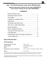
Page 2: ...19 120V SCHEMATICS 20 BASIC SPECIFICATIONS CS100 Subwoofer Frequency Response 6dB 30Hz 120Hz Amplifier Output 150W RMS 300W Peak Driver 10 254mm Dimensions H x W x D including feet 18 1 2 x 12 3 4 x 15 470mm x 324mm x 381mm Weight 41 lb 18 6kg The Peak Dynamic Power is measured by recording the highest center to peak voltage measured across the output of a resistive load equal to minimum impedance...

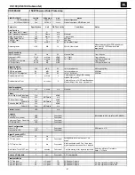
Page 3: ...2 Volume max using RMS reading DMM VOM or A P Residual Noise Floor 1 mVrms max 2 Volume max w A P Swept Bandpass Measurement Line freq harmonics Input Impedance Line input L R LFE 10 K ohms n a Nominal Filters Left Right Low Pass fixed Hz 2dB Order Q 4th dB Octave n a LFE Low Pass fixed Hz 2dB Order Q 2nd dB Octave n a Subsonic filter HPF Hz 2dB Order Q 2nd dB Octave n a Limiter yes no YES n a Fea...

Page 4: ...e voltage Protection Short Circuit Protection YES Functional Direct short at output Thermal Protection 65 deg C Functional 1 8 max unclipped Power Back panel temperature rise should not exceed 35K rise DC Offset Protection YES Functional DC present at Speaker Out leads Relay or crowbar for driver fire protection AC Line Fuse Rating 120VAC 3 15 Amps Type T or Slo Blo Fuse markings T3 15A 250V Exter...

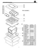
Page 5: ...CS100 CS6100 Subwoofer PACKAGING 4 ...

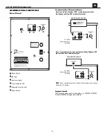
Page 6: ... W att s SUBWOOFER OR LFE OUTPUT RECEIVER PROCESSOR 15 4 5m Subwoofer cable included If your receiver processor does not contain a Dolby Digital or DTS processor but has a subwoofer output NOTE If your receiver processor has only one sub out you may use either the L or R input 15 4 5m Subwoofer cable included RI SK O F ELECTRI C SHO CK DO NO T O PEN CAUTIO N RI SK O F ELECTRI C SHO CK DO NO T O PE...

Page 7: ... nonoperation e g when you are away on vacation Adjust Level Turn the Subwoofer Level Control 5 up about halfway If no sound emanates from the subwoofer check the AC line cord and input cables Are the connectors on the cables making proper contact Is the AC plug connected to a live receptacle Has the Power Switch 6 been pressed to the ON position Once you have confirmed that the subwoofer is activ...

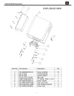
Page 8: ...CS100 CS6100 Subwoofer EXPLODED VIEW 7 ...

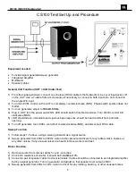
Page 9: ...en immediate and vigorous bass response should be heard and felt from port tube opening 6 Turn off generator turn LEVEL control full counterclockwise MIN and disconnect RCA cable Sweep Function 1 Follow steps 1 5 above using a sweep generator as a signal source 2 Sweep generator from 20Hz to 300Hz Listen to the cabinet and drivers for any rattles clicks buzzes or any other noises If any unusual no...

Page 10: ...CS100 CS6100 Subwoofer 9 ...

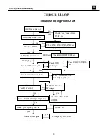
Page 11: ...red Check Fuse Transformer D501 etc Check RY101 D110 Q112 Q113 etc Check CLASS 150W MODEL Check VCC VCC DC voltage Check Q107 Q108 Q109 etc Check Q501 Q502 Q503 D502 etc Check Q206 Q207 U203 etc Check U202 pin8 signal Check U201 pin1 signal Test R147 signal Check M100 signal The Amp ass y OK END CheckU201 U202 VR201 etc Check limiter Circuit C317 Check U301 R343 R344 C340 Q301 Q302 etc Check TH1 C...

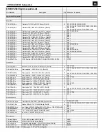
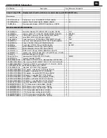
Page 12: ... 2 C221 C222 130 2b221k503 e Disc capacitor 220P 50V 10 RoHS 9 C207 C208 C210 C211 C212 C214 C220 C230 C249 130 3f104z503 e Disc capacitor 0 1U 50V 80 20 RoHS 8 C232 C242 C244 C245 C246 C252 C254 C256 130 ch220k503 e Disc capacitor 22PF CH 50V 10 RoHS 1 C229 132 103j503 e Mylar capacitor 0 01uF 50V 5 RoHS 2 C223 C224 132 104ja03 e Mylar capacitor 0 1UF 100V 5 RoHS 1 C218 132 223ja03 e Mylar capaci...

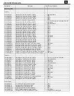
Page 13: ...1 6W 1 MF 26mm RoHS 1 R318 110 20332jk3 e Resistor 3 3K 2W 5 standing short feet 7 5m RoHS 1 R134 113 50s68j00 e cement Resistor 0 068Ω 5W 5 horizontal RoHS 1 R147 116 201001jk3x e oxidation foil Resistor 1 00K 2W 5 standing 7 5mm RoHS 1 R148 116 304700jk2x e oxidation foil Resistor 470Ω 3W 5 clip feet 10mm RoHS 2 R501 R502 Capacitors 130 3f104z503 e Disc capacitor 0 1U 50V 80 20 RoHS 6 C107 C117 ...

Page 14: ... R28 118 12063902j e SMD Resistor 39 0K 1206 5 RoHS 1 R3 118 12064700j e SMD Resistor 470Ω 1206 5 RoHS 1 R8 118 12064701j e SMD Resistor 4 70K 1206 5 RoHS 3 R1 R5 R12 118 12064702j e SMD Resistor 47 0K 1206 5 RoHS 1 R17 118 12064704j e SMD Resistor 4 70M 1206 5 RoHS 1 R4 118 120647r0j e SMD Resistor 47 0Ω 1206 5 RoHS 2 R20 R21 Capacitors 141 c0101k50 e SMD capacitor 100pF 50V 10 1206 NP0 RoHS 1 C4...

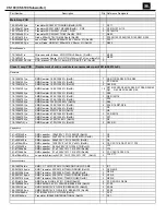
Page 15: ... pin CE 1 RoHS 1 180 pbr12c11s e power switch PUSH BR12C11S RoHS 1 SW501 193 201815t2 e ceramic insulator RoHS 2 302 AL 05092 0LAE Rear board 270 215 2 5T al black printing CSC100 120V 1 306 ABS 00004 0BAE Rear housing REAR CABINET 268 213 102 A B S UL RoHS 1 311 ABS 00028 0BAE Plastic knob 46077 W soft material P V C RoHS LEVEL 1 317 000 00037 0LAE earth end M3 solder t 0 3 RoHS 1 323 AL 00056 0L...

Page 16: ...CS100 CS6100 Subwoofer 15 ...

Page 17: ...CS100 CS6100 Subwoofer 16 ...

Page 18: ...CS100 CS6100 Subwoofer 17 ...

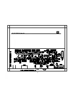
Page 19: ...CS100 CS6100 Subwoofer 18 ...

Page 20: ...CS100 CS6100 Subwoofer 19 ...

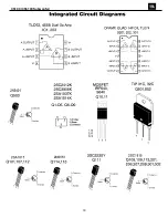
Page 21: ...CS100 CS6100 Subwoofer 20 ...

Page 22: ...CS100 CS6100 Subwoofer 21 ...

Page 23: ...CS100 CS6100 Subwoofer 22 ...

Reviews: