4 5 . 7 5
D E T E C T O R
L 6
J 1 0
I N P U T / O U T P U T
V I D E O
O U T P U T
I F I N P U T
J 1
I F P R E A M
Q 1
V R 7
A G C A D J U S T
S O U N D I F
D E T E C T O R I C 2
4 . 5 M H z
D E T E C T O R
L 1 2
4 . 5 M H z
D I S C R I M I N A T O R
L 1 6
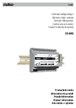
Figure 17 - IF Module
IF Module
The IF Module shown in
Figure 17
plugs into
the Tuner Interface Panel. Caliouts point to the
major components and adjustments, the Video IF
Input jack, J1, is shown in the upper left
portion of the diagram. Located to the right: L2
47.25MHz Adjacent Channel Sound Trap, F1 Saw
Filter, Q1 IF Pre-Amp, IC1 Video IF/Detector,
L6 and L7 respectively, Q3 Equalizer, and the
Input/Output connector J10. To the left: Q4
Video Output, AGC Adjust VR7, IC2 Sound
Detector, L16 45.75MHz Detector Coil, and L12
4.5MHz Discriminator.
As seen in
Figure 18,
the IF cable from the
Tuner is connected to the If Module at J1. The
Adjacent Channel Sound signal is trapped at
47.25MHz by C1/L2; then, the signal is
amplified by Q1 and fed to SAW Filter F1, where
two bandpass curves shape the Video IF and Sound
IF responses. The Video response is notched at
the 41.25MHz Sound carrier and fed to IC1 for
amplification detection. After detection, the
Video signal is passed through a 4.5MHz trap to
remove all traces of the sound carrier. About
2Vpp Sync-negative, Composite Video is output
from Q4 to the Tuner Interface Panel and through
Video Buffer Q15. The buffered Video is fed to the
Input/Output Panel.
The second response of the SAW Filter
suppresses Video sidebands and passes the Video
and Sound IF carriers. The two carriers drive
IC2, which detects the 4.5MHz difference signal,
or Sound carrier. The Sound carrier is
amplified, limited, and quadrature detected into
wideband Audio. The Audio output signal, with an
amplitude of about 0.5 volts RMS, is coupled to
the Stereo/SAP Decoder.
Summary of Contents for 6810
Page 3: ...Figure 1 Signal Flow Block Diagram...
Page 15: ...Figure 14 TS10 Tuning System Block Diagram...
Page 20: ...Figure 20 Decoder Module Signal Flow Diagram...
Page 30: ...Figure 31 Comb Filter Module Figure 32 Comb Filter Circuit...
Page 35: ...Figure 37 CRT Drive Circuit 4...
Page 41: ...Figure 47 Keystone Trapezoid Generator o Figure 48 Side Pincushion Generator...