


450
400
350
300
250
150
100
50
200
Power
Temp
17:14
JBC Net
USB fl ash drive is connected.
Station is controlled by a PC.
Station is controlled by a robot.
System Notifications
Station software update.
Press INFO to start the process.
Warning.
Press INFO for failure description.
Error.
Press INFO for failure description,
the type of error and how to proceed.
The following icons will be displayed on the screen’s status bar.
JT-A
TC
Suction
OK
17:14
20
ºC
Power
45%
120ºC Selected
TC
Temp.
4m 38s
400
ºC
80
%
400ºC Selected
Protection
Hot Air Temp.
Air Flow Selec.
TC
Suction
OK
17:14
20
ºC
Power
45%
120ºC Selected
TC
Temp.
4m 38s
400
ºC
80
%
400ºC Selected
Protection
Hot Air Temp.
Air Flow Selec.
By pressing
Graphics
in the main MENU, temperature and power fi gures in real time
are displayed. This helps you decide which nozzle to use to obtain the best quality
solder joints.
Graphics
Temperature
Power (%)
External
Temp.
Ext. temp
Export Graphics
Insert a USB flash drive into the USB-A
connector to save your soldering process
in csv format.
The fi rst system to optimize traceability in soldering
- Get greater quality and control in your production
- Manage your whole soldering process remotely in real time
Station Update
Download the JBC Update File from
www.jbctools.com/software.html
Insert the USB flash drive with the file down-
loadedto the station.
Files
Update
Point
2/5
Temp
250
ºC
Flow
60
%
Time
2m 30s
3m 18s
Hot Air Temp
240
ºC
ºC
%
Ext. TC Temp
20
Air Flow
80
3m 18s
· Add point
· Delete point
· Load profile
· Save profile
· Exit
Current
Air
Temp.
Data for
These Points
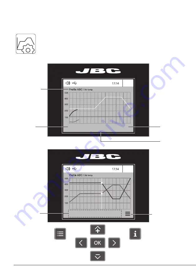
Profile
Name
Current
Air flow
Current
External
TC Temp.
In this mode you can
set up or edit
as many as 25 profiles of temperature and air flow.
Edit Mode
Menu
Options
Profiles
Advanced Functionalities
To work with profiles it is essential to use RWB / RWS / RWT rework arms. The
Rework Arms supports the Hot Air Heater maintaining the distance and position to
the component.
6


