background image

USER  MANUAL 


Chapter 2 Overview of DVR 


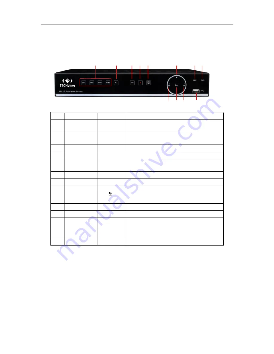
2.1 Front Panel


SN 

Key or indicator  Identification 

Functions 

Power indicator 

PWR 

If  the  “Green”  indicator  is  on,  DVR  is  getting  power 
normally. 

HDD indicator 

HDD 

If  the  “Red”  indicator  flashes,  the  hard  drive  is  being 
read or written to. 

Up key 


Move up 

Menu key 

MENU/ESC 

Enter into the main menu/Return 

Manual 

recording key 

● 

Start manual recording 


II 


ALL 

Multiple display mode


    8 

CH1    CH2 

CH3    CH4 


Single channel selection(4-Channel DVR) 

USB 


USB port 

10 

Right key 

/


Move right; Fast forward at various speed 

11 

Confirmation key 

PTZ 

Enter into PTZ menu; Confirm operation; Edit 

12 

Left key 

/


Move left; Fast backward at various speed 


11 

10 

12 


Summary of Contents for qv-3146

Page 1: ...USER MANUAL 1...

Page 2: ...IZZARD 5 4 3 MAIN INTERFACE 6 CHAPTER 5 DVR MENU 7 POPUP MENU 7 5 1 MAIN MENU GUIDE 8 5 2 MAIN MENU 9 5 2 1 PARAMETER 9 5 2 2 Record Search 17 5 2 3 Device 21 5 2 4 PTZ and Cloud Storage 22 5 2 5 Syst...

Page 3: ...3 7 System 41 6 3 8 Advanced 43 6 3 9 Local Setting 46 6 3 10 Logout 46 CHAPTER 7 APPENDIX 47 7 1 TROUBLESHOOTING 47 7 2 USAGE MAINTENANCE 48 7 3 SYSTEM CONNECTION DIAGRAM 49 7 4 ACCESSORIES GOODS IN...

Page 4: ...the authorized dealer or service center 7 Do not try to remove the upper cover Warning Do not remove the cap of DVR so as to avoid electric shock 8 Handle with care If DVR does not work normally becau...

Page 5: ...eo input and the signal input from external alarm apparatus Network operation Support authorized accessing of remote client to ensure the system security Mouse operation Support USB mouse operation to...

Page 6: ...s being read or written to 3 Up key Move up 4 Menu key MENU ESC Enter into the main menu Return 5 Manual recording key Start manual recording 6 II 7 ALL Multiple display mode 8 CH1 CH2 CH3 CH4 Single...

Page 7: ...etwork port Connect with LAN Ethernet and RJ45 port 8 RS 485 Sensor Alarm RS485 Sensor Alarm port Connect by referring to the interface definition below 9 Power port Connect with the power supply DC12...

Page 8: ...otection 3 2 IP Camera and Monitor Connection DVR video output signals are transmitted to VGA monitor or HDMI monitor by VGA or HDMI cable and DVR video can be monitored Refer to section 1 2 Rear Pane...

Page 9: ...will enter into the DVR system initializing screen shown as Picture 4 1 Picture 4 1 4 2 Startup Wizzard After DVR startup is completed the startup wizard will be displayed If you do not want to make...

Page 10: ...mat and overwrite type Picture 4 5 4 3 Main Interface Picture 4 6 Note When internal HDD is not connected to DVR the character H will appear on the lower part of the main interface and accompany buzze...

Page 11: ...Menu Now you could perform parameter setting and operate on Main Menu Multi screen Auto Cruise Record Search Sequence Volume setting and Brightness setting shown as Picture 5 1 The options in the pop...

Page 12: ...hutdown Main Menu Private Zone Parameter Network Record Alarm Record Search Event Search Device General Users Info Log Schedule Mainstream FTP Email Substream Email Schedule DDNS RTSP Motion Alarm Rec...

Page 13: ...n Set the position for the channel display Color Click Setup to enter into the color setting page Picture 5 4 Image hiding Enable or disable the channel real time monitoring Show Time Enable or disabl...

Page 14: ...ght click the mouse to return to the Privacy Zone page 4 Click Save to save the setting Picture 5 6 Picture 5 7 4 Record Go to Main Menu Parameter Record Record to enter into the interface shown as Pi...

Page 15: ...w stands for motion record 3 Red stands for alarm record Main Menu Record Mainstream Mode Support 960H and D1 Select a resolution save and exit main menu Then the system will automatically restart to...

Page 16: ...After restarting DVR or DHCP server the IP address obtained by DVR may be different As a result user shall check IP address and port number for each remote access of DVR The operation procedure is as...

Page 17: ...chedule Go to Main Menu Parameter Network E mail Schedule to make Email schedule as shown in Picture 5 14 Picture 5 14 Select the channel and the date to be set One week s schedule can be set The reco...

Page 18: ...number When using DDNS domain name to access DVR user shall confirm that the port can be normally connected to current IP on the public network and the settings for server address host name user passw...

Page 19: ...leted right click the mouse button to return and click Save to make the parameter setting effective Record Channel When object motion is detected the record channel setting will be activated Channel E...

Page 20: ...n Detection When IP camera detects object moving alarm will be activated Sensitivity is subject to the actual application environment test Sensitivity is adjusted according to the sensitivity of movin...

Page 21: ...time The default setting is from 0 00 to 24 00 Playback Channel Click a date and select corresponding channel in Playback Channel The selected channels shall not be more than 16 as shown in Picture 5...

Page 22: ...Control bar Click the icon to zoom in certain area of the playback screen and right click mouse to return the Playback page See Picture 5 28 2 Events Go to Main Menu Record Search Events to enter into...

Page 23: ...es to the computer 2 Open playback player and click or For example if you want to choose 264 add backup file and select a file to play as shown in Picture 5 32 and 5 33 Picture 5 32 Picture 5 33 If yo...

Page 24: ...to play at 2 4 8 16 speed Open file Full screen display Never on top Always on top On top during playing Screenshot Save path installation directory Video Client Capture Adjust volume Add folder or f...

Page 25: ...only when HDD is Normal Free Total Space Remaining or total space of HDD Free Time Remaining time for HDD recording according to currently set Resolution Encoding Rate and Frame Rate of image Auto ove...

Page 26: ...ctures Enable Motion Detection to get captured pictures for motion detection 4 DriName refers to the name created in the folder of Dropbox and the name can be defined by the user e g CloudDVR000 The f...

Page 27: ...step 8 Enter the folder to view the DVR captured pictures 5 2 5 System 1 General Go to Main Menu System General General to enter into the interface shown as Picture 5 40 Picture 5 40 2 DST Go to Main...

Page 28: ...cture 5 43 User Name consists of 8 characters and password is composed by number 0 9 with max length of 8 numbers Set user password Administer is authorized to set user common user s authority as show...

Page 29: ...e 5 45 6 Info Go to Main Menu System Info to enter into the interface shown as Picture 5 46 Picture 5 46 7 Log Go to Main Menu System Log as shown in Picture 5 47 Picture 5 47 User may search log info...

Page 30: ...returns back to Preview mode with no any operation within the set auto maintain time 2 Events Go to Main Menu Advance Events to enter into the interface shown as Picture 5 49 Picture 5 49 Auto Reboot...

Page 31: ...word on the login interface to unlock Default User Name admin Password blank The login interface is as shown in Picture 5 51 Picture 5 51 Note Administrator has all authorization of menu operation and...

Page 32: ...e toolbar to start sequence Chapter 6 Web Application Manager 6 1 ActiveX control download and installation Open your web browser and input the IP address and Web port number of DVR such as http 172 1...

Page 33: ...ew select it to open all live pictures Press Login to log in client and remotely visit DVR The default password is blank and administer is authorized to modify the password Set password as per introdu...

Page 34: ...a single live interface Volume switch Record switch the remote record switch of client Record will be automatically saved to a specified position on PC after the function is enabled Snapshot Capture...

Page 35: ...option and select Exit Full Screen 2 Video Control Picture 6 5 Adjust the chromaticity of video Adjust the brightness of video Adjust the contrast of video Adjust the saturation of video 6 3 2 Playbac...
Page 36: ...tum as shown in Picture 6 8 On the time axis red part stands for alarm record yellow stands for normal record and original part stands for no record during this period Picture 6 8 Before playback choo...

Page 37: ...channel mode Snap Quad mode Download Full Screen Open all the playback channels Stop playing all the playback Table 6 1 Record file clip After opening playback click icon to clip the selected file an...

Page 38: ...file you want to download and click Start download System will download the record file in sequence and save to local PC The downloading file will be displayed in percentage form After downloading fi...

Page 39: ...ode See Picture 6 13 Picture 6 13 2 Privacy Zone Each channel can set 4 privacy zones as shown in Picture 6 14 The relevant parameters should be consistent with DVR local setting Select zones to be de...

Page 40: ...hown in Picture 6 17 The relevant parameters should be consistent with DVR local setting Picture 6 17 6 3 4 Network Unfold Network to show its sub options Network Email and DDNS configuration as shown...

Page 41: ...eters should be consistent with DVR local setting Picture 6 19 3 Email Email Set DVR alarm Email configuration parameters including Email address SSL Email Enable Interval and Email Schedule etc Detai...

Page 42: ...DNS user should make sure port and current IP can be normally connected in public network Details settings including server address host user and password should be consistent with NVR local setting P...

Page 43: ...e Sensitivity Alarm out Alarm Record and Alarm Capture etc Detailed setting should be consistent with DVR local setting See Picture 6 24 Picture 6 24 2 I O Alarm Set parameters for I O Alarm Alarm Out...

Page 44: ...heck HDD status of DVR and overwritten time Detail setting should be consistent with DVR local setting Please refer to Picture 6 26 Picture 6 26 2 PTZ User may set the relevant parameters of PTZ Detai...

Page 45: ...6 28 1 and 6 28 2 Picture 6 28 1 Picture 6 28 2 6 3 7 System Click System option to unfold its sub options General Users and Information 1 General User may check DVR language and video system and set...

Page 46: ...tailed setting should be consistent with DVR local setting Please refer to Picture 6 30 Picture 6 30 3 Information User may search device name device number device type MAC address software version IE...

Page 47: ...wn in Picture 6 32 Picture 6 32 Updating procedure Firstly select the update file path The file format is sw Please refer to Picture 6 33 Picture 6 33 Secondly click Start to start updating The updati...

Page 48: ...Trip Line setting Perimeter It refers to the prohibited area with any shape set by user in the field of view In the area the appearance and entry of the specified type of target will be detected The s...

Page 49: ...local setting Refer to Picture 6 38 Picture 6 38 7 OSC Exception Detection OSC includes two functions i e legacy detection and lost detection OSC can set up to 4 rules in a channel and each rule can b...

Page 50: ...cord and Playback clip file Download Path for remote file Snapshot Path for captured pictures Interval for switching record files Packaging time and File type H264 and AVI shown as Picture 6 40 Pictur...

Page 51: ...aiming the remote controller at the IR receiver on front panel If it still doesn t work please check if the batteries in the remote controller are dying If not check if the remote controller is broken...

Page 52: ...to scheduled recording or manual recording Then you may stop recording by the prescribed methods And another way of stopping recording is to set channel as Off status in record setting 7 2 Usage Maint...

Page 53: ...USER MANUAL 49 7 3 System Connection Diagram 7 4 Accessories Goods in kind prevail USB mouse CD Warranty Card Power Adapter Good in kind prevail User Mannual Remote Conroller...

Page 54: ...ut no guarantee is given as to the correctness of its contents We do not undertake any responsibility for the harms cause by using our product The model of the products in the user s manual only for r...

Reviews: