8
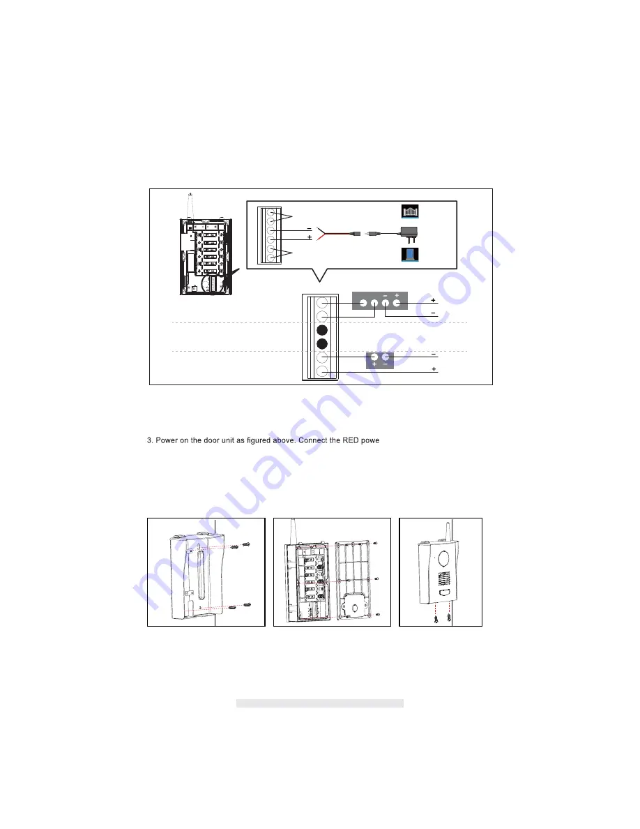
INSTALLATION VIA DC POWER MODE
1. Remove the back cover of door unit.
2. (Optional) The door unit supports two types of third-party locks, 4-wire type and 2-wire type (please
note the door unit do not supply the power to the 3rd party locks). If you want to control the door
lock via the receiver, please follow the wire connection method in the figure above.
r wire to the terminal block with
"DC+" symbol. Connect the Black power wire to the terminal block with "DC-" symbol. Then plug
the power adapter to the DC IN jack and wall outlet.
4. Optional: The door unit has been paired to the receiver by factory default. If you need to pair the
door unit to the system again, please go to "Advanced Settings / Camera Setup" for more details.
5. Install the door unit in proper location.
Dry Contact A - Related icon
Dry Contact B - Related icon
A. 4-Wire Type Connection Diagram
Power
Power
Input
B. 2-Wire Type Connection Diagram
Adaptor connect to DC Jack
Step1
Use the sunshield as a
template
to drill 4 suitable
holes and attach
the sunshield
to the wall with the
screws
and wall plugs (supplied).
Step2
Install the back panel to the door
unit with the correct screws
(supplied).
Step3
Position the door unit into
the sunshield and finish the
installation with the two
anti-theft screws (supplied).
Summary of Contents for QC3624
Page 14: ...13...
Page 15: ...14 SETUP MASKING AREA 1 Save Exit 2 Block grid 3 Unblock grid...
Page 16: ...15 EVENT LIST 1 Previous Page 2 Next Page 3 Return 4 Folder Date DATE...
Page 17: ...16 Press folder and hold on 2 seconds 5 Delete 6 Cancel Date Folder...
Page 18: ...17 TIME 1 Return 2 Folder Time 3 Delete 4 Cancel Press folder and hold on 2 seconds...
Page 19: ...18 File 5 Previous Page 6 Next Page 7 Return 8 File 9 Delete 10 Cancel...
Page 23: ...22 ALARM BUZZER Alarm Buzzer setting of receiver...
Page 26: ...25 MEMORY CARD OVERWRITE...


