background image

JAVELIN MACHINERY (AUSTRALIA)

J800 /J900 OPERATION MANUAL

(incl. Troubleshooting Machine Problems)

JULY 2016

Page 4

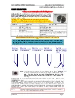
KNIFE SELECTION

~ always use cut resistant gloves when handling knives ~

KNIFE BEVELS When slitting narrow widths only a primary bevel is required
but with wider widths a back bevel is needed to balance the forces on either
side of the knife so that it will cut straight through the roll without deflecting
(See note re bevels below)

CAUTION: Knife may be damaged or shatter if insufficient back bevel on knife
when slitting wide widths. Trying to slit a roll to a wide width from a tightly wound

log roll, using a knife with insufficient back bevel, risks chipping or shattering the knife.

Diagram No.

Slitting range

Knife requirements

1

Up to 22 mm (7/8”)

No Back Bevel

2

25.4 mm (1”) - 38 mm (1½”)

0.5 mm (1/64”) Back Bevel

3

40 mm (1 5/8”) - 96mm (4”)

1.5 mm (1/16”) Back Bevel

4

Over 100mm (4”)

Equal Bevel both sides of knife

5

Any width (very hard materials)

Tightly wound denser rolls will require test slitting to determine
the best knife bevel & edge for product Additional angle on
primary bevel

Dense materials that will not displace

Must be rewound to a lesser tension

THE ABOVE DIMENSIONS ARE A GUIDE ONLY AND WILL VARY ACCORDING TO THE DENSITY OF THE MATERIAL TO BE

SLIT.

Diagram 1:
Knife with no
back bevel

Diagram 2:
Knife

with

0.5mm

(1/64”)back bevel

Diagram 3:
Knife

with

1.5mm

(1/16”)back bevel

Diagram 4:
Knife with equal
bevel both sides

Diagram 5:
Knife with reinforced
edge (No. 2 angle)
(refer to manual for
details)

NOTE: A rounded edge is preferred for most adhesive tapes.

Some exceptions

would be, for example, foam sealant & paper tapes which require a sharp
edge.

Too sharp an edge can result in edge breaking down (chipping).

Edge should be slightly rounded with Shielded oil stone to prevent this
occurring.

KNIFE DIAMETER The rule is to use the smallest diameter knife possible to minimise any run out. Using a dial indicator, check
the knife for excessive run out.
KNIFE BEVELS

.The primary bevel on each knife has a long bevel at 8º with a smaller bevel at the outer edge of the knife at

11º to strengthen knife edge. All Javelin grinders are factory set to 11º and care must be taken for this not to change. We
recommend knives be either ground on your machine or returned to Javelin in order to maintain 11º bevel. Knives sent to
contractors may result in bevel angle being changed with resultant slitting problems. To ensure knives are sharpened to the edge
we suggest running a thin mark around the outer edge with a black pental pen. This mark will disappear once the knife has been
sharpened to the edge.

NOTE

:

It is imperative records be kept for specific materials so the operator knows which knife to choose each time a particular
product is to be slit. Ref: Operator Reference Sheets in the Manual.

No. 1 angle

No. 2 angle

1 - 2mm (1/16” - 3/32”)

**With interlined materials it may be necessary to glue end of log roll to prevent centre of roll moving out,
also if tightly wound a Diagram 3 bevel may be required. (Ensure log roll is pushed up against chuck face
or spacer roll)

Summary of Contents for J800

Page 1: ...hinery Australia A C N 005 543 411 ABN 18 005 543 411 Email sales javmach com au Website www javelinmachinery com au HEAD OFFICE PO Box 805 GLEN WAVERLEY Vic 3150 Australia Phone 61 3 8786 3614 Model J800 900 MANUAL SINGLE KNIFE SLITTER JULY 2016 OPERATION MANUAL INCL TROUBLESHOOTING MACHINE PROBLEMS ...

Page 2: ... a lesser tension or the material cut on a machine known as a slit rewinder Knife parameters are crucial in successful Single Knife Slitting Refer Knife Selection Section As widths being slit increase so must the secondary or back bevel on the knife in order to balance the forces and achieve a straight cut Failure to pay attention to choosing a knife with the correct bevel will result in the knife...

Page 3: ...ife and rolls when loading or unloading ENSURE knife is in its furthest back position 4 KEEP the area around the machine CLEAN and DRY proof surface or mats Only the operator to work within area designated by hazard tape 5 ENSURE main isolator is switched OFF before any maintenance is carried out 6 USE suitable PROTECTIVE GLOVES when handling blades 7 Ensure KNIFE IS REMOVED OR KNIFE EDGE COVERED ...

Page 4: ...th the two spanners supplied do not overtighten NOTE The knife is engraved and must be positioned on the spindle with TOP uppermost and the two lines pointing to the mandrel 6 Set knife forward stroke Bring knife edge gently against mandrel Adjust knife forward stop black knob behind knife pedestal see Fig 2 7 until knife is about 3mm 1 8 off mandrel 7 Set knife grinder back to ensure it will not ...

Page 5: ...Diagram 5 Knife with reinforced edge No 2 angle refer to manual for details NOTE A rounded edge is preferred for most adhesive tapes Some exceptions would be for example foam sealant paper tapes which require a sharp edge Too sharp an edge can result in edge breaking down chipping Edge should be slightly rounded with Shielded oil stone to prevent this occurring KNIFE DIAMETER The rule is to use th...

Page 6: ...at main isolating switch and using a Shielded Oil Stone see Fig 3 3 1 hold the stone flat against knife ege and slowly rotate the knife with the other gloved hand This will have the effect of dulling the sharp edge Polish knife edge with Scotch Bright IMPORTANT NOTE If knife is slightly chipped you will need to retun it to JAVELIN for repair The knife grinder on this machine is not intended for he...

Page 7: ...er Width Length Core size Material thickness Mandrel Speed Width To Be Cut Density Of Material Tolerance Required Weight of Log Roll Knife Diameter Thickness No of Backing Plates Back Bevel Size Note As a general rule prior to selecting knife required check notes on previous page Knife Drive if fitted On Off Knife Braking On Off Knife Edge Rounded Sharp Sprays Off On Chuck Grip Internal External S...

Page 8: ...d lever is pushed all the way back until the knife clears the diameter of log ready for indexing to the right for the next cut SET UP AND OPERATION PROCEDURE 1 Load log roll onto mandrel Slide log roll up to chuck face and raise mandrel support arm 2 Expand the mandrel to secure log roll by turning clockwise the black knob at the right hand end of machine Use chuck pins as alternative to gripping ...

Page 9: ...ousing Allan Bradley Variable Speed Drive Only on Fully Optioned Machines Main Electrical Cabinet Operator Control Panel 6 Speed Controller for chuck mandrel Digital Electronic Length Counter 4 Chuck ON OFF Button 5 Knife ON OFF Button Located at rear of machine on older models Control Panel NOTE Control Panel Configuration may vary from machine to machine depending on options The panel shown is f...

Page 10: ...control tightness density and a mechanical counter to measure desired length of finished material The jumbo or master roll is loaded on the unwind shaft and is threaded over its idler roller and under the spreader bar inspection roller if fitted The leader is taped on a core on the expanding mandrel ready for rewinding The spreader bar on the unwind stand should be adjusted so that it contacts the...

Page 11: ... core lock into core use rubber mallet if necessary then tighten in same manner as LH core lock Load unwind shaft on roller guides making sure that disc brake is between the pneumatic brake pads Lock unwind shaft with toggle clamp on both ends and replace lock pin on a chain Material threading diagram ref to Fig 4 2 Fig 4 3 then tape leader on to the core on the mandrel Ensure material is square t...

Page 12: ...he adjustable index stop is set to 38mm or 1 this width can be achieved continuously by rotating the index handle between the two stops If a greater width is required the index handle can be lifted and traversed rapidly For a precise width of cut stop the index handle just before the required width and turn knurled handle at centre of index plate firmly but slowly until desired dimension is met Ch...

Page 13: ...idth accuracy is required ii to verify the width set on the index dial iii can be more convenient to use instead of the indexing dial when slitting very wide widths ie 76mm 3 and over Electronic digital counter displays width to be slit NOTE As an alternative to the dial indexer when slitting wide widths the operator can advance the knife down the machine by raising the knurled black handle and re...

Page 14: ...at the grinding wheel is approximately central across the width of knife bevel 5 Start knife motor 6 Switch grinder ON Adjust grinder travel stop gradually so that grinding wheel touches the knife evenly and continues to grind until the knife is sharpened right to the cutting edge and mark from felt pen removed 7 Use the dressing stick to clean the face of the grinding wheel if it becomes dirty or...

Page 15: ... knife drive motor is switched off by trip dog 5 Trip dog is mounted on knurled knob 2 When sharpening knife brake must be off trip dog is not to be in contact with switch 7 otherwise knife drive motor will not turn on KNIFE LUBRICANT SYSTEM when fitted The knife spray is used to keep heat down which results from friction between the knife and the material being slit and to prevent adhesive build ...

Page 16: ...with rubber sleeves to protect the knife edge from the steel mandrel Log roll is gripped by turning the black knob clockwise to expand the pin holders jaws inside the mandrel The knob is located at the right hand end of the machine protruding from the motor cover NOTE When rotating the black knurled knob to release the expansion jaws to remove slit rolls it may be necessary to tap the knob with a ...

Page 17: ... air supply Valve turned off Flow control shut Pedestal on rear stop Air but not water Check Water pick up tube is pushed into bottle Water bottle is full Flow valve adjustment Loose fitting or split tubes Air pressure of flow rate too high forcing water back into bottle Water pick up filter blocked NOTE Low grade detergents cause rust can congeal and block tubes Javelin has sourced a good quality...

Page 18: ...ays Slit rolls difficult to remove from Mandrel Worn or rough fibre strip Poor quality cores Replace fibre strip Use plastic cores if possible Rolls sticking together Insufficient Lubrication Incorrect knife Check sprays Ref Operator Reference Sheet Chuck spindle becoming warm Lack of lubrication between non rotating mandrel and chuck spindle Grease mandrel through chuck Remove mandrel and lubrica...

Page 19: ...Core ID oversize Log roll out of round Knife forward stop not set correctly Replace sleeve Use correct core size Slow mandrel speed if possible Set knife close to mandrel Slit rolls difficult to remove from Mandrel Worn Mandrel Sleeves Core I D undersized Replace Sleeve Purchase undersized sleeves from Javelin Strands protruding from rubber mandrel sleeve Knife cutting too deep Adjust knife depth ...

Page 20: ...utwards in bearing housing lock grub screws Replace housings and bearings Knife not slitting through core and or knife cutting into mandrel at one end of machine Mandrel support not aligned parallel to knife carriage Raise mandrel support Traverse carriage to extreme right Adjust forward knife stop so that the knife just touches mandrel Traverse knife to the extreme left and move knife forward to ...

Page 21: ...screws b Loosen bearing housing retaining bolts c Move either or both bearing housings outwards to create approximately 020 5mm between the bearings and the spacer tube d Tighten bearing housings and nip grub screws Grub screws in both bearings must be in line axially e Tighten spindle locknut and then the grub screws This will preload the bearings in the housings with no axial float NOTE Brake ba...

Page 22: ...tor See Note iv Runout should not be more than 08mm 003 If runout exceeds tolerance mark backing plate in 2 positions and one position on spindle with marking pen v Rotate backing plate to position 2 and re check if runout is excessive 1 2 3 4 backing plate spindle CHECKING FOR KNIFE RUNOUT Place dial indicator on knife face 1 at top Picture A and rotate knife to 2 Picture B A run out of not more ...

Page 23: ...e and grub screws are tightened the sleeves will not move Ensure that there is no clearance between collar and sleeve NOTE To maximize longevity of mandrel sleeves ensure knife is set approximately 2 3mm away from OD of sleeve When operator pulls the cutting handle down the knife should then fractionally penetrate the sleeve Mandrel Sleeve Tan These sleeves cover steel mandrel The sleeves are easy...

Page 24: ... red sleeve Push on new sleeve to hold jaws in position Remove tape and tap sleeve home to correct position IMPORTANT NOTE RED SLEEVE Over an extended period the red expanding sleeve may develop a bulge and make it difficult to slide log rolls over the red sleeve To prevent this we recommend that you occasionally loosen the grub screw in the retaining collar Fig 2 and slide the sleeves down the ma...

Page 25: ...Imperial or Metric 11 DIGITAL COUNTER WIDTH DISPLAY when fitted 12 KNIFE GRINDER FUNCTION 13 HOW TO SHARPEN THE KNIFE 13 KNIFE BRAKE when fitted 14 KNIFE LUBRICANT SYSTEM when fitted 14 ROTATING EXPANDING MANDREL 15 TROUBLE SHOOTING MACHINE PROBLEMS 16 KNIFE LUBRICANT SYSTEM Venturi 16 MANDRELS 17 FIXED MANDRELS NON ROTATING 17 EXPANDING MANDRELS 18 MANDREL SUPPORT ARM 19 SLITTING TOLERANCES 20 CH...

Reviews: