background image

3-18


Maxor Operator’s Manual

www.javad.com

S E T U P   A N D   M E A S U R I N G

Measuring with the Maxor

3

Setting up an RTK Rover

Use the following steps to set up an RTK Rover station. You should 
already have programmed the modem.

1. Set up the Rover station receiver's antenna as described in “Maxor 

Receiver Setup” on page 3-2.

2. Connect your receiver and computer. See “Connecting the Maxor 

and a Computer” on page 2-9 for this procedure.

3. Click 

Configuration->Receiver

.

4. Select the 

Positioning

 tab and set the Position Masks, Elevation 

mask (degrees) parameter to 15 (Figure 3-10 on page 3-15).

5. Select the 

Rover

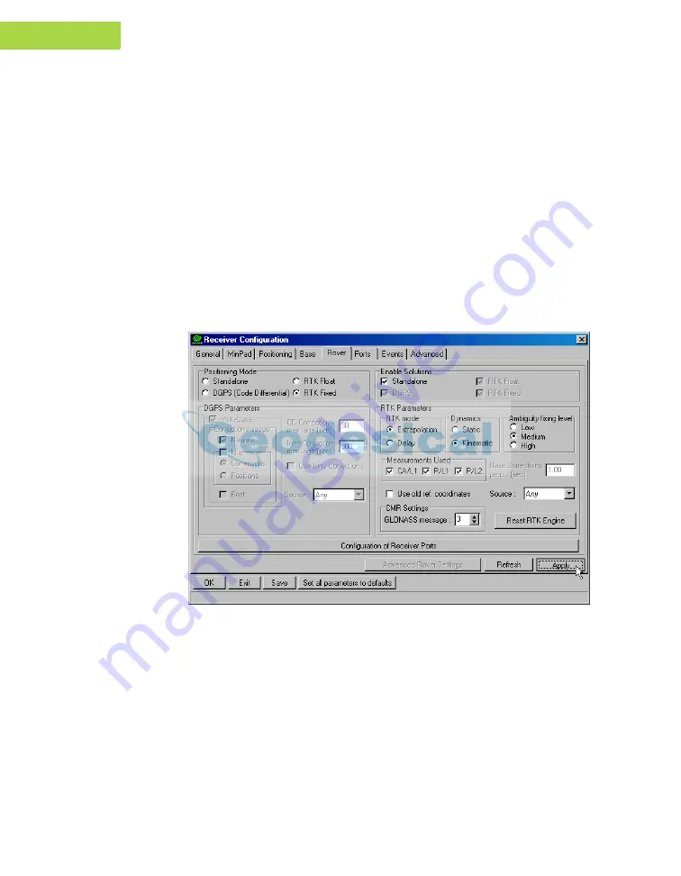
 tab and set the desired Positioning Mode 

(Figure 3-13).

Figure 3-13. Rover Tab Configuration

Adjust the following RTK Parameters settings:

• Under RTK mode in the RTK Parameters section, choose either 

Extrapolation for RTK (kinematic) or Delay for RTK (static).

–Extrapolation is for low-latency, high frequency output (>= 5 Hz) 
RTK applications. The rover will extrapolate the base station's 
carrier phase measurement corrections when computing the rover's 
current RTK position.

–Delay is for 1 Hz high precision RTK applications. The Rover 
RTK engine will compute either a delayed RTK position (for the 

Summary of Contents for Maxor

Page 1: ...nc January 2006 All contents in this manual are copyrighted by JNS All rights reserved The information contained herein may not be used accessed copied stored displayed sold modified published or distributed or otherwise reproduced without express written consent from JNS ...

Page 2: ......

Page 3: ...nce xiv FCC Class B Compliance xiv Canadian Emissions Labeling Requirements xv Manual Conventions xv Screen Captures xvi Chapter 1 Introduction Overview 1 2 Principles of Operation 1 3 GPS Overview 1 3 Calculating Positions 1 4 GPS Positioning 1 4 Conclusion 1 5 Receiver Overview 1 5 Maxor Accessory Kit 1 6 Cables 1 7 Software 1 7 Literature 1 8 ...

Page 4: ...figuration Powering the Maxor 2 2 Internal Batteries 2 2 External DC Power Source user supplied 2 2 Battery Charger 2 3 Power Management 2 4 Charging the Maxor 2 8 Connecting the Maxor and a Computer 2 9 Establishing a Wireless Connection 2 9 Establishing an RS232 Cable Connection 2 10 Establishing a USB Cable Connection 2 10 Establishing a PCView Connection 2 11 Maxor Configuration 2 14 MinPad Co...

Page 5: ...GSM GPRS integrated with 2W UHF transceiver with Modem JNS 2 35 Configuring a Rover Station s internal GSM GPRS integrated with 2W UHF transceiver with Modem JNS 2 36 Configuring a single GSM GPRS Modem 2 37 How to configure a sigle GSM GPRS modem with PCView 2 38 How to configure a single GSM GPRS modem with FieldView 2 39 Bluetooth Module Configuration 2 40 Collecting Almanacs 2 44 Chapter 3 Set...

Page 6: ...em 4 6 Single GSM GPRS radio modem 4 6 Information Modes 4 7 Normal 4 7 Extended Information Mode EIM 4 7 Downloading Files to a Computer 4 9 Deleting Files 4 12 Checking an OAF 4 13 Loading OAFs 4 15 Managing Receiver Memory 4 16 Clearing the NVRAM 4 17 Using MinPad to Clear NVRAM 4 17 Using PCView to Clear NVRAM 4 18 Changing Receiver Modes 4 19 Sleep Mode 4 19 Zero Power Mode 4 19 Checking Firm...

Page 7: ...endix A Creating Scripts A 1 Specifications A 1 Appendix B Receiver Specifications B 2 General Details B 2 GPS Board Details B 7 Bluetooth Module Details B 9 Internal JNS UHF Modem Details B 9 Optional GSM GPRS Module Details B 10 Connector Specifications B 12 Radio Modem RF Connector B 12 Power Connector B 12 Serial RS 232C Connector B 13 USB Connector B 14 GPS External Antenna RF Connector B 15 ...

Page 8: ...perator s Manual www javad com TAB LE O F C O N TE NT S Appendix C Safety Warnings C 1 General Warnings C 1 Internal Battery Pack Warnings C 2 Usage Warnings C 2 Appendix D UHF Radio Usage D 1 Warranty Terms D 1 ...

Page 9: ...er Mode 2 5 Select Charger Mode 2 5 Select Power Output Modes Ports 2 6 Select Power Output Modes Slots 2 6 View Voltages Information 2 6 Enable Slots 2 7 Activate Low Power Mode 2 7 PCView Main Window 2 11 Bluetooth and RS232 Connection Parameters 2 12 USB Connection Parameters 2 12 PCView Connection Established 2 13 Configuration Receiver 2 14 Receiver Configuration 2 15 Receiver Configuration M...

Page 10: ...on Port and Click Connect 2 41 BTCONF Identification Tab 2 42 BTCONF Parameters Tab 2 42 BTCONF Security Parameters 2 43 BTCONF Serial Interface Tab 2 43 Chapter 3 Setup and Measuring Maxor GD and Maxor GGD Antenna Offsets 3 3 MarAnt Antenna Offset Measurements 3 5 Configuration Receiver 3 6 Select External Antenna Option 3 6 Configuration Receiver MinPad 3 8 Advanced Multipath 3 9 Advanced Loop M...

Page 11: ...1 Delete Files 4 12 Tools Receiver Options 4 13 Option Manager 4 14 Load OAF 4 15 Tools Clear NVRAM 4 18 Help About 4 21 About PCView 4 21 Floader Main Screen 4 23 Set Device Type 4 24 Program Tab Settings 4 24 Set Device Type 4 25 Program Tab Settings 4 25 Get Device Type 4 26 Program Tab Settings 4 27 Bluetooth Firmware Load Complete 4 27 Appendix A File Manual Mode A 1 Appendix B Power Connecto...

Page 12: ...viii Maxor Operator sManual www javad com Notes ...

Page 13: ...ty instructions before operating inspecting or adjusting Always wear the required protectors safety shoes helmet etc when operating the receiver COPYRIGHT All information contained in this Manual is the intellectual property of and copyrighted material of JNS All rights are reserved You may not use access copy store display create derivative works of sell modify publish distribute or allow any thi...

Page 14: ...TA LOSS OF PROFIT SAVINGS OR REVENUE OR LOSS OF THE PRODUCT S USE IN ADDITION JNS IS NOT RESPONSIBLE OR LIABLE FOR DAMAGES OR COSTS INCURRED IN CONNECTION WITH OBTAINING SUBSTITUTE PRODUCTS OR SOFTWARE CLAIMS BY OTHERS INCONVENIENCE OR ANY OTHER COSTS IN ANY EVENT JNS SHALL HAVE NO LIABILITY FOR DAMAGES OR OTHERWISE TO YOU OR ANY OTHER PERSON OR ENTITY IN EXCESS OF THE PURCHASE PRICE FOR THE MAXOR...

Page 15: ... Confidentiality Information confidential In the event you become legally compelled to disclose any of the Confidential Information you shall give JNS immediate notice so that it may seek a protective order or other appropriate remedy WEBSITE OTHER STATEMENTS No statement contained at the JNS website or any other website or in any other advertisements or JNS literature or made by an employee or in...

Page 16: ...that may cause undesired operation This equipment has been tested and found to comply with the limits for a Class B digital device pursuant to Part 15 of the FCC rules These limits are designed to provide reasonable protection against harmful interference in residential installations This equipment generates uses and can radiate radio frequency energy and if not installed and used in accordance wi...

Page 17: ...B respecte toutes les exigences du Réglement sur le matériel brouilleur du Canada Manual Conventions This manual uses the following conventions Tip Supplementary information that can help you to configure maintain or set up a system Notice Supplementary information that can have an affect on system operation system performance measurements or personal safety CAUTION Notification that an action has...

Page 18: ...MSTANCES SHOULD THIS ACTION BE PERFORMED Screen Captures This manual includes sample screen captures Your actual screen can look slightly different from the sample screen due to the receiver you have connected operating system used and settings you have specified This is normal and not a cause for concern ...

Page 19: ... its features and physical elements Also a brief description of the principals of GPS operation is presented This information is split into the following sections Overview 1 2 Principles of Operation 1 3 Receiver Overview 1 6 Maxor Accessory Kit 1 7 Getting to Know Your Maxor 1 9 Option Authorization File OAF 1 16 ...

Page 20: ...tem satellites of the United States and the GLONASS Global Navigation Satellite System satellites of the Russian Federation increasing the number of satellites your receiver can detect thus improving the accuracy of your measuring points increasing productivity and reducing cost The dual frequency and GNSS features of the Maxor combine to provide the only real time kinematic RTK system accurate fo...

Page 21: ...ndard 15 degree angle up to 10 or 12 GPS satellites are visible from any point on earth When a receiver can also track GLONASS satellites between 10 and 16 satellites are visible For information on the current status of the GPS constellation visit http tycho usno navy mil or http www navcen uscg gov For GLONASS visit http www glonass center ru frame html Despite numerous technical differences in t...

Page 22: ...d GLONASS satellites in view does not exceed twenty 20 Once locked on to a satellite the receiver collects ephemerides and almanacs saving this information to its NVRAM Non Volatile RAM GPS and GLONASS satellites broadcast ephemeris data cyclically with a period of 30 seconds GPS satellites broadcast almanac data cyclically with a period of 12 5 minutes GLONASS satellites broadcast almanac data cy...

Page 23: ... Earth This overview simply outlines the basics of GPS and GLONASS positioning For more detailed information visit the JNS website http www javad com Receiver Overview When power is turned on and the receiver self test completes the receiver s 20 channels initialize and begin tracking visible GNSS satellites Each of the receiver s channels can be used to track C A L1 P L1 or P L2 signals The numbe...

Page 24: ... results obtained in the field Depending on your options capabilities of the receiver include Common Tracking Multipath reduction Wide area augmentation system WAAS Adjustable phase locked loop PLL and delay lock loop DLL parameters Dual frequency static kinematic real time kinematic RTK and differential GPS DGPS measuring modes Auto data logging Setting different mask angles Setting different mea...

Page 25: ...dView Software and software manuals are also available on the JNS website http www javad com The following software will also be useful for operating caring for and using your Maxor receiver and may be required for some applications FLoader JNS s firmware loader available from the JNS website Modem JNS JNS s modem configuration software available from the JNS website PDLCONF from Pacific Crest fir...

Page 26: ...T is 159 mm wide 162 mm deep and 115 mm hightm weighs 1 620 kg 1 760 kg with UHF modem Maxor is versatile receiver and can be configured in several different ways depending on the usage and function of the receiver at the jobsite The casing allocates space for two no removable on board Li Ion batteries and two Euro cards One of those cards is the GPS GNSS receiver and the other is used for communi...

Page 27: ... with one of the following communication boards however your receiver may also be configured without a radio modem UHF modem a Pacific Crest PDL Positioning Data Link modem either a 450 470 MHz or 430 450 MHz receiving only UHF transeiver a Javad Navigation Systems 2 Watts transceiver for 410 470 MHz optional to UHF could be added an integrated GSM GPRS module for Europe or USA GSM a single dual b...

Page 28: ...rmation The batteries will not charge in this mode The power board s processor and firmware are independent of the receiver card To ensure firmware compatibility the GPS receiver board and power board must be loaded with firmware from the same package GNSS Receiver Board The Maxor is supplied depending on the desired receiver functionality with a Euro 80 or Euro 112 card Maxor GGDT is supplied wit...

Page 29: ...at least 17 hours for the Maxor GD GG or 14 hours the Maxor GGD The Li Ion batteries used in the Maxor should run at no less than 98 capacity after 500 charging cycles These batteries do not need to be drained before recharging A battery charger AC adapter is included with the standard package See Specifications on page B 1 for technical specifications on the battery External Components The Maxor ...

Page 30: ...U C T I O N Getting to Know Your Maxor 1 Figure 1 2 Maxor Radome Bottom Panel Figure 1 3 shows the Maxor s bottom panel components Antenna Reference Point ARP The GPS GLONASS external antenna connector standard configuration Figure 1 3 Maxor Bottom Panel ...

Page 31: ...ial ports Port A used for communication between the Maxor and a controller or any other external device Port B used internally to connect the receiver board with the Bluetooth module Port C used internally to connect the modem and receiver boards Port D used for communication between the receiver and an external device Vent plug Equalizes the pressure between the inside of the receiver and the out...

Page 32: ...ction This is a BNC female connector for UHF modems or a TNC female connector for GSM modems Event optional The BNC event marker connector provides event input synchronized with a specified reference time 1PPS optional The BNC connector for 1 pulse per second 1PPS generates 1PPS signals with programmable reference time period and offset synchronized to a specified reference time Antenna optional E...

Page 33: ...ns remain intact when clearing the NVRAM or resetting the receiver The OAF enables the following kinds of functions For a complete list of available options and details visit the JNS website http www javad com or consult your dealer Type of signal standard L1 optional L2 Memory standard 0 MB for Maxor GD GG optional up to 512 MB for Maxor GGD optional up to 1 GB Update rate standard 1Hz optional 5...

Page 34: ...1 16 Maxor Operator s Manual www javad com Notes ...

Page 35: ...Connecting the Maxor and a Computer 2 9 Maxor Configuration 2 14 MinPad Configuration 2 19 Radio Configuration 2 26 Bluetooth Module Configuration 2 54 Collecting Almanacs 2 58 Chapter Tip Before you can use your Maxor receiver you need to 1 Charge the batteries See Charging the Maxor on page 2 8 2 Configure the various parts of your receiver See Connecting the Maxor and a Computer on page 2 9 Max...

Page 36: ...ource The use of external power source allows you to continue using the receiver in case the internal batteries are discharged The appropriate external power source must provide 6 to 28 V DC and must Table 2 1 Average Operating Times Modem Type Mode Maxor GG GD Maxor GGD Maxor GGDT Any Off 17 hours 14 hours 18 hours UHF On and in Receiving mode only 15 hours 12 hours 16 hours UHF On and in 1 Watts...

Page 37: ... 2 Plug the power cable into the receiver s power port 3 Attach the battery clip to the battery Battery Charger The same charger used to charge the internal batteries can be used as an external power supply for the receiver The charger is provided with the standard receiver package To use power from the battery charger connect the equipment as follows Figure 2 1 on page 2 4 Plug the Receiver to SA...

Page 38: ...ower supply is used and the batteries are not being charged Blinking once a second an external power supply is used and the batteries are being charged Power Management Use JNS s PCView software to manage the receiver s power The complete description of PCView exceeds the scope of this manual but can be found in the PCView Software Manual The latest copy of this software and the manual can be down...

Page 39: ...2 Select Power Mode Auto receiver automatically selects the power source Mix receiver automatically detects and consumes power from the source with the largest voltage Battery A receiver consumes power from battery A Battery B receiver consumes power from battery B External receiver uses an external power supply 5 Select the Charger Mode drop down list to set the desired charger mode Figure 2 3 Cu...

Page 40: ...e power board delivers voltage on pin one of all serial port connectors even if the receiver is off 7 Select the Power output modes Slots drop down list to set power output on internal slots Figure 2 5 Figure 2 5 Select Power Output Modes Slots On all slots have power if the receiver is turned on Off internal slots do not have power even if the receiver is turned on Always internal slots have powe...

Page 41: ...On Ports displays the voltage output on pin one of all serial ports connectors 9 Select and check each of the Turn on off Slots check boxes to enable the corresponding internal slots Figure 2 7 Figure 2 7 Enable Slots 10 Select and check the Enable Low Power Mode check box to put the receiver s processor into low power consumption mode Figure 2 8 Figure 2 8 Activate Low Power Mode 11 Click Apply ...

Page 42: ...ver is in Normal mode for charging The receiver will not charge in Zero Power Mode see Zero Power Mode on page 4 19 for more information Turn off the receiver by pressing and holding the green power key for more than one and less than four seconds until both STAT and the REC LEDs turn off Leave overnight Fully charging the batteries takes approximately seven hours The internal batteries cannot be ...

Page 43: ...r receiver contains Bluetooth wireless technology that allows file transfer and synchronization between the receiver and any other external device that supports Bluetooth wireless technology for example an IPAQ or a computer with USB to Bluetooth adapter or PCMCA to Bluetooth adapter installed Notice Changing the receiver s Port B default settings will affect the Bluetooth link The default setting...

Page 44: ... 4 In the Turn on off Slots area ensure the Slot 3 B check box is enabled Establishing an RS232 Cable Connection 1 Using the RS232 cable connect the serial port of your computer usually COM1 to the receiver s serial port A 2 Press the power buttons on the receiver and computer to turn them on 3 Continue with Step 1 in Establishing a PCView Connection on page 2 11 Establishing a USB Cable Connectio...

Page 45: ... 1 Once the receiver and a computer are connected start PCView on your computer The PCView main screen displays Figure 2 9 Figure 2 9 PCView Main Window Notice that the lower left hand corner shows the receiver status as Disconnected 1 On the Connection Parameters dialog box select the following parameters and click Connect For Bluetooth or RS232 connections Figure 2 9 on page 2 11 Set the Connect...

Page 46: ...ction Parameters For USB connections Figure 2 11 Set the Connection mode Direct Set the port for your computer USB from the Port drop down list Select the receiver s ID from the Rec ID drop down list Figure 2 11 USB Connection Parameters Once a PCView connection with the receiver has been established the current communications settings such as port name baud rate if applicable and flow control if ...

Page 47: ...perator s Manual 2 13 C O NFIGU R AT I O N Connecting the Maxor and a Computer of the main window of PCView A timer begins to count up in the lower right corner as well Figure 2 12 Figure 2 12 PCView Connection Established ...

Page 48: ...PCView Software Manual to manage all possible Maxor receiver configurations The following configuration is recommended for the most common applications However you can select configuration parameters as needed for your particular jobsite Notice Click Apply after making any configuration change otherwise the receiver will not accept the change 1 Connect your receiver and computer See Connecting the...

Page 49: ...IGU R AT I O N Maxor Configuration Figure 2 14 Receiver Configuration 3 Click the MinPad tab configure the following settings and click Apply Figure 2 15 on page 2 16 Set the Recording interval in seconds Set the Elevation mask for Log file in degrees ...

Page 50: ...r Figure 2 15 Receiver Configuration MinPad Tab If your jobsite is in an area that has obstructions buildings trees etc and or the antenna location is near reflective objects configure the receiver to reduce errors from these sources 4 Click the Advanced tab on the Receiver Configuration screen and then click the Multipath Reduction subtab Enable the following boxes and click Apply Figure 2 16 on ...

Page 51: ...uction Figure 2 16 Advanced Configuration Multipath Reduction 5 Click the Loop Management tab enable the following boxes and click Apply Figure 2 17 Enable Common Tracking Static Mode used for static receivers only disable if using the receiver as a Rover Figure 2 17 Advanced Configuration Loop Management ...

Page 52: ...screen 7 Click on File Disconnect and then File Exit to quit PCView Notice Disconnecting the receiver from the computer before exiting will eliminate any possible conflict in the management of your serial ports Once the receiver is configured the configuration will remain until you change it either using PCView or clearing the NVRAM ...

Page 53: ...or Zero power mode Turn data recording on or off FN key Change the receiver s information mode Show the number of GPS green and GLONASS orange satellites being tracked STAT LED Show data recording status REC LED Show each time data records to internal memory REC LED Show the status of post processing mode static or dynamic when performing a Post Processing Kinematic measuring with the help of FN k...

Page 54: ...x enable RTS CTS handshaking Figure 2 19 and then click Connect Figure 2 19 Connection Parameters RTS CTS Handshaking 4 Click Configuration Receiver Figure 2 20 Figure 2 20 Configuration Receiver 5 Click the MinPad tab set the following parameters and click Apply Figure 2 21 See the following pages for descriptions of these parameters Recording interval on page 2 21 Elevation mask for log file on ...

Page 55: ...s data logging This setting is used not only when logging a single log file but also when logging receiver data in AFRM mode Values are 1 86400 seconds The default value is one second Elevation Mask for Log File parameter This parameter specifies the minimum elevation angle for the satellites whose data will be put in the receiver files logged when pressing FN The default value is five degrees Fil...

Page 56: ...File Rotation Mode AFRM parameters JNS receivers are capable of automatically rotating log files During a file rotation event the receiver closes the current file and opens a new one according to a user defined schedule The Period and Phase parameters specify this schedule File rotation launches the moment the receiver time module Period is equal to Phase More precisely a new log file opens immedi...

Page 57: ...eiver will erase the file with the earliest file creation time date AFRM must be enabled to use this FIFO First In First Out feature The default value is off disabled FN Key Mode parameter You use these two radio buttons to program how the receiver will react when pressing the FN key LED blink mode switch pressing FN will toggle between the MinPad s normal extended information modes and start stop...

Page 58: ...or Before Power Failure Enabled Radio Button Results Off On Always 1 Receiver data logged to file specified Data logging will not resume when power is restored Receiver will resume data logging to the same file when power is restored Receiver will resume data logging to the same file when power is restored 2 Receiver data logged to default file Data logging will not resume when power is restored A...

Page 59: ... Operator s Manual 2 25 C O NFIGU R AT I O N MinPad Configuration After pressing the Power key to turn on the receiver After resetting the receiver with PCView or the Reset key After taking the receiver out of Sleep Mode ...

Page 60: ...d com Notice Your receiver may be configured without a radio modem If this is the case please skip to Bluetooth Module Configuration on page 2 40 Configuring a JNS 2W UHF 410 470 radio transceiver Modem JNS is JNS s radio modem configuration utility for modems embedded in Maxor family receivers Modem JNS provides the following functions Connecting a PC to an integrated radio modem via a serial por...

Page 61: ...410 470 radio transceiver provides TX RX UHF communications between a Base Station and Rover To configure the UHF radio modems have the following ready Computer running Windows 98 or newer Modem JNS version 1 7 or newer Serial cable or Bluetooth wireless technology capabilities 1 Connect the computer and receiver using an RS232 cable or Bluetooth wireless technology 2 Turn on the receiver 3 Open M...

Page 62: ...s at your jobsite are manufactured by Javad Navigation Systems PDL Select this protocol if you use PDL radio modem s together with JNS radio modem s at the jobsite 2 From the Modulation Type control Figure 2 23 on page 2 28 select a modulation scheme that will be used by your base radio modem It can be either 4 Level FSK Frequency Shift Keying or GMSK Gaussian Minimum Shift Keying Figure 2 23 Modu...

Page 63: ...ing error control in data transmission FEC adds redundant check bits to the data stream reducing data throughput If you are going to use FEC and a format of differential messages requires a great deal of data e g RTCM 2 x transmitted over the radio link it is recommended to select 19200 4 Level FSK This will ensure reliable radio communication between the base and rover receivers 7 From the Protoc...

Page 64: ...must be used for both the receiver and the modem Figure 2 24 Serial Interface Tab 11 Click Apply then click on File and select Disconnect If you want to close the program click File Exit 12 Start PCView and set up the receiver to run as an RTK Base Station For how to set up an RTK Base using PCView refere to Setting up an RTK Base Station on page 3 13 and PCView Software Manual Set Radio Link Para...

Page 65: ...time with the Select all and Deselect all controls Notice For FCS to operate properly you must select at least two frequencies 5 In the Time Out edit box specify a period in seconds with which the base radio modem will send a service word to the rover radio modem Notice It is recommended to make Time out larger by 2 3 seconds than the period of transmitting differential corrections 6 In the Noise ...

Page 66: ... modem will start using this frequency for data transmission Otherwise the radio modem will continue the scan process throughout the frequency list until the frequency with an acceptable amount of noise is found 7 Click the Serial Interface tab see Figure 2 24 on page 2 30 and select a baud rate for the modem s serial port The same rate must be used for both the receiver and the modem 8 Click Appl...

Page 67: ...st be the same for base and rover 4 For a maximum data communication reliability select the Forward Error Correction check box 5 Set the protocol mode from the Protocol Mode control use the same protocol as at the base station 6 From the Output Power control see Figure 2 22 on page 2 28 set the level of RF transmit power to 10 mW 7 Click the Serial Interface tab Figure 2 24 on page 2 30 and select...

Page 68: ...frequencies at one time with the Select all and Deselect all controls Notice For FCS to operate properly you must select at least two frequencies Also the selected frequencies must be the same as at the base radio modem 5 In the Time Out edit box specify a period in seconds within which the rover radio modem will listen to the incoming data on the current operating frequency Should there be no any...

Page 69: ...how to set up an RTK Base using PCView refere to Setting up an RTK Rover on page 3 18 and PCView Software Manual Warning When finished configuring the radio modem always disconnect from Modem JNS before exiting to prevent conflicts with serial port management Configuring a Base Station s internal GSM GPRS integrated with 2W UHF transceiver with Modem JNS 1 Repeat steps 1 4 described on page 2 27 2...

Page 70: ...elect Disconnect If you want to close the program click File Exit 9 Start PCView and set up the receiver to run as an RTK Base Station For how to set up an RTK Base using PCView see Setting up an RTK Base Station on page 3 13 and refer to PCView Software Manual Warning When finished configuring the GSM module always disconnect from Modem JNS before exiting to prevent conflicts with serial port man...

Page 71: ... 30 8 Click Apply then click on File and select Disconnect If you want to close the program click File Exit 9 Start PCView and set up the receiver to run as an RTK Rover Station For how to set up an RTK Rover using PCView see Setting up an RTK Rover on page 3 18 and refer to the PCView Software Manual Warning When finished configuring the GSM module always disconnect from Modem JNS before exiting ...

Page 72: ...rt you can use an USB cable and a computer with the JNS USB driver installed this driver is available to download from Free Software section of Support area on http www javad com 2 Start PCView on your computer Once a connection between the receiver and computer has been established change PCView to Manual Mode Figure 2 29 Figure 2 29 File Manual Mode 3 Execute the following receiver commands from...

Page 73: ...c sndtime 2 Command 6 Set the required modem mode set par modem c mode master for the receiver configured as a rover set par modem c mode slave for the receiver configured as a base The manual mode screen will show RE002 in response to each of these commands When finished you should have seven responses in the manual mode window s reply panel 4 Now the receiver is completely ready for field operat...

Page 74: ...wing folder C Program Files JNS BTCONF 2 Download btconf zip from the JNS website http www javad com and unzip it into the BTCONF folder This file contains Btconf exe the executable file for the Bluetooth module configuration program To uninstall or remove BTCONF delete any applicable BTCONF directories or folders and any BTCONF shortcuts Once you have BTCONF available follow these steps to config...

Page 75: ...ft corner select the computer serial port used for communication Figure 2 31 Figure 2 31 Select Communication Port and Click Connect 5 Click Connect to connect the computer and Bluetooth module Figure 2 31 Once the receiver and computer connect through BTCONF the Identification tab Figure 2 32 on page 2 42 displays the following information Bluetooth name the name of the Bluetooth module set in th...

Page 76: ...b sets identifying and security information for your Bluetooth module The security section allows you to set data security and unauthorized access parameters for the Bluetooth module Figure 2 33 BTCONF Parameters Tab 7 Enter up to 14 characters to set a unique name for the Bluetooth module Figure 2 33 and click Apply 8 To set security parameters Figure 2 33 on page 2 42 enter and enable the follow...

Page 77: ...re two Bluetooth enabled devices such as the receiver and a computer can establish a communication link The two devices must use the same PIN Notice If you do not need security settings leave these parameters disabled Figure 2 34 BTCONF Security Parameters 9 Click the Serial Interface tab Figure 2 35 Enable Echo to display Bluetooth module replies and corresponding commands on the computer termina...

Page 78: ... if needed in a location with a clear view of the sky 2 Turn on the receiver Wait for about 15 minutes while the receiver collects almanac data from satellites Notice If 15 minutes have passed and the receiver does not lock on to satellites you may need to clear the NVRAM See Clearing the NVRAM on page 4 17 for this procedure You will need to collect or update the almanac If the receiver has been ...

Page 79: ...iguration 2 Set up your Base or Rover station See Step 1 on page 3 2 3 Measure the antenna height See Step 2 on page 3 2 for internal antennas or see External Antenna Setup on page 3 4 for external antennas 4 Begin collecting data See Step 3 on page 3 4 All Maxor receivers include an internal micro strip antenna This antenna is able to capture L1 L2 signals from GPS and GLONASS satellites Also you...

Page 80: ...tant and in surveys for horizontal location only Horizontal surveys are often larger in area than can reliably fit on a flat plane therefore the antenna adjustment must be done in three dimensions and then projected onto a two dimensional plane The receiver calculates the coordinates of the antenna s phase center To determine the coordinates of the station marker the user must specify the followin...

Page 81: ...ter of the antenna This is analogous to the point at which a distance meter measures in a prism A user must enter the prism offset to compensate for this point not being at a physical surface of the prism In the case of a GPS GLONASS antenna the offset is entered depending on the type of measurement taken For vertical the offset is simply added to the measured vertical height to produce a true ver...

Page 82: ...ites to ensure good quality data The process of locking on to satellites normally takes less than one minute In a new area under heavy tree canopy or after resetting the receiver it may take several minutes Step 3 Collect Data 1 To begin collecting data press and hold the FN function key for more than one second and less than five seconds 2 Release the FN key when the REC recording LED light turns...

Page 83: ...ce point ARP located on the bottom of the antenna at the base of the mounting threads Slant measured from the marker to the lower edge of the antenna s slant height measure mark SHMM MarAnt antenna offsets are shown in Figure 3 2 Offset measurements for this antenna is given in Table 3 2 Figure 3 2 MarAnt Antenna Offset Measurements Table 3 2 Antenna Offset Measurements Antenna Radius A Vertical O...

Page 84: ...et to Auto allowing the receiver to detect automatically the available antenna whether internal or external If you have changed this setting or the receiver does not detect the external antenna use the procedure below to set the External Antenna detection option 1 Connect your receiver and computer See Connecting the Maxor and a Computer on page 2 9 for this procedure 2 Start PCView 3 Click on Con...

Page 85: ... each end of a baseline during a certain period of time These two receivers track four or more common satellites have the same data logging rate 5 30 seconds and the same elevation mask angles The length of the observation sessions can vary from a few minutes to several hours The optimal observation session length depends on the user s experience as well as the following factors The length of the ...

Page 86: ... completes data the receivers collect can be downloaded onto a computer and processed using post processing software for example Ensemble The procedure that follows describes the steps the operator should take to perform a Static Measuring using MinPad 1 Connect your receiver and computer See Connecting the Maxor and a Computer on page 2 9 for this procedure 2 Open PCView click Configuration Recei...

Page 87: ...en the Multipath tab set the following parameters then click Apply Figure 3 6 on page 3 9 Code Multipath Reduction enable Carrier Multipath Reduction enable Figure 3 6 Advanced Multipath 4 Click the Loop Management tab and set the following parameters then click Apply Figure 3 7 on page 3 10 Enable Common Tracking enable ...

Page 88: ...g You can use the kinematic measuring method in two ways Stop and go measuring Kinematic continuous trajectory measuring Stop and Go Measuring The stationary receiver Base station is set up at a known point such as a measuring monument The receiver continually tracks the satellites and logs the raw data into its memory The rover receiver is set up at an unknown point and collects data in static mo...

Page 89: ...e 3 8 Rover MinPad Configuration Notice Remember both Base and Rover receivers must collect data from common satellites at a common data recording rate and with identical elevation mask angles 3 Set up the Rover at an unknown point and press power Allow the Rover to collect static data for two to ten minutes The REC LED will be orange 4 Check the STAT light for satellites tracked 5 When finished p...

Page 90: ... the starting point the rover will not need to be initialized The determination of ambiguity parameters is carried out while the rover is moving and is called on the fly ambiguity resolution Furthermore if loss of lock occurs such as an obstruction that prevents a clear view of the sky the receiver will be re initialized on the fly After the measuring completes raw data collected by the receivers ...

Page 91: ...e information such as differential corrections is transmitted in real time from a Base station to one or more Rover stations Setting up an RTK Base Station To configure an RTK Base station using PCView take the following steps 1 Set up the Base station receiver s antenna as described in Maxor Receiver Setup on page 3 2 2 Connect an external modem to port D for the Maxor receiver 3 Press the power ...

Page 92: ...7 Click the Set all parameters to defaults button located at the bottom of the Receiver Configuration screen Figure 3 9 Figure 3 9 Set All Parameters to Defaults 8 On the Receiver Configuration screen select the MinPad tab Specify desired settings Refer to the PCView Software Manual for more information ...

Page 93: ...eters Figure 3 11 on page 3 16 GPS GLO at one time enable Antenna position enter Lat Lon and Alt values Do one of the following If known type in the values Click Get from receiver Enable Averaged and enter the Averaged Span in seconds then click Apply Click Tools Reset receiver and wait until the specified interval span completes Examine the Base coordinates on the Base tab they should correspond ...

Page 94: ...guration 11 Select the Ports tab and set the following port parameters Figure 3 12 on page 3 17 Use serial port C for an internal PDL and GSM modem Output drop down list select type and format of differential corrections Period sec enter interval at which receiver will generate differential corrections Baud rate drop down list select a baud rate i e the rate at which differential messages will be ...

Page 95: ...witching the modem to the transmitting mode 13 When finished with the previous steps press the power button on the external modem 14 Select the radio transmission power using the Low High toggle on the rear panel of the modem When in High the AMP PWR LED will be on 15 Use the Channel button to set the frequency channel Check that the modem transmits the corrections the TX LED will blink red each t...

Page 96: ... and set the Position Masks Elevation mask degrees parameter to 15 Figure 3 10 on page 3 15 5 Select the Rover tab and set the desired Positioning Mode Figure 3 13 Figure 3 13 Rover Tab Configuration Adjust the following RTK Parameters settings Under RTK mode in the RTK Parameters section choose either Extrapolation for RTK kinematic or Delay for RTK static Extrapolation is for low latency high fr...

Page 97: ... RTK engine uses the ambiguity fix indicator when making decisions whether or not to fix ambiguities Low Medium and High correspond to the indicator s 95 99 5 and 99 9 states respectively The higher the specified confidence level the longer the integer ambiguity search time 6 Select the Ports tab and set the following parameters for Serial C Figure 3 14 Input drop down list select desired differen...

Page 98: ... RTK float where the Rover receiver computes the current relative coordinates in differential mode using both pseudo ranges and phases however with a float solution the phase ambiguity is not a fixed integer number and the float estimate is used instead RTK fixed where the Rover receiver computes current relative coordinates with ambiguity fixing in differential mode The LQ field reflects the stat...

Page 99: ...ng standard Maxor operating procedures Using MinPad 4 2 Downloading Files to a Computer 4 9 Deleting Files 4 12 Checking an OAF 4 13 Loading OAFs 4 15 Managing Receiver Memory 4 16 Clearing the NVRAM 4 17 Changing Receiver Modes 4 19 Checking Firmware Version 4 21 Loading New Firmware 4 23 ...

Page 100: ...g the power key turns the receiver on and off Status LED When the receiver is on and no satellites are tracked the STAT LED will blink red When satellites are tracked the STAT LED will produce one blink for each tracked satellite green for GPS orange for GLONASS Reset Key Pressing the reset key for about one second causes a hard reset of the receiver the receiver to leave Zero Power Mode and retur...

Page 101: ...n or orange If the REC LED is red the receiver has run out of memory has a hardware problem or contains an improper OAF see Option Authorization File OAF on page 1 14 for more information on OAFs The REC LED blinks green or orange each time data is written to the internal receiver s memory You set the data recording time interval using PCView See Recording Interval parameter on page 2 21 for infor...

Page 102: ...a recording is OFF and the FN key is Not pressed No light No data recording Orange blink Internal file system test in progress Red No free memory hardware problem with data recording Pressed for 1 second If FN key mode is LED blink mode switch Orange Release to charge information mode If FN key mode is Occupation mode switch Orange No function Pressed for 1 5 seconds If FN key mode is LED blink mo...

Page 103: ...ted post processing occupation mode undefined If FN key mode is Occupation mode switch Green Data recording started Kinematic post processing occupation mode Orange Data recording started Static post processing occupation mode Pressed for 1 second If FN key mode is LED blink mode switch Orange Release to change information mode If FN key mode is Occupation mode switch Orange Release to toggle betw...

Page 104: ...axor receiver may be equipped with a different modem type e g with PDL from Pacific Crest or with JNS 2W UHF 410 470 radio transceiver or with single GSM GPRS radio modem The color of the RX LED indicates if the modem has power is receiving signals or is turned off The RX LED shows status of the modem s operation JNS 2W UHF 410 470 radio transceiver No light the modem is turned off Solid green the...

Page 105: ...mode the receiver continues to work as usual but the STAT LED indicates the following extended information Delimiter an easily distinguishable double blink that shows the overall status of tests performed in EIM The STAT LED color for delimiter is calculated from the colors of other STAT LED blinks Orange at least one blink is orange Red no orange blink and at least one red blink Green all other c...

Page 106: ...able Green receiver passed the test Red receiver failed the test 1 To switch to EIM press and quickly release within one second the FN key on the MinPad 2 Watch for the delimiter double blink With good receiver antenna and observation conditions all blinks should be green within 15 minutes of powering on Green ok Orange wait Red some tests failed 3 To switch back to normal press the FN key ...

Page 107: ...puter ensures that no files are lost You should download files as soon as possible after collecting data at the jobsite PCView provides a File Manager to download files to your computer and delete files from the Maxor 1 Connect your receiver and computer See Connecting the Maxor and a Computer on page 2 9 for this procedure 2 Start PCView 3 On the Connection Parameters dialog box enable RTS CTS ha...

Page 108: ...ch to download and store files Or type a new folder name and click Create to create a new folder in which to download and store files Open this new folder 7 Select the Download files tab 8 Select the file s you want to download Figure 4 5 To select multiple files hold down the shift key and click on nonsequential files to select several files at once or hold down the Ctrl key and click on individu...

Page 109: ...ay next to each file Figure 4 6 Blue indicator file in queue for downloading Red indicator file currently downloading Green indicator file has successfully downloaded Figure 4 6 Download Files Status Indicators 10 When finished click Exit on the File Manager dialog box 11 Continue with other operations Or click File Disconnect then File Exit to quit PCView ...

Page 110: ... 4 Click File File Manager See Figure 4 3 on page 4 9 5 On the Download files tab select the file s you want to delete Figure 4 7 To select multiple files hold down the shift key and click on nonsequential files to select several files at once or hold down the Ctrl key and click on individual files Figure 4 7 Delete Files 6 Click Delete Figure 4 7 7 Click Yes at the delete files confirmation dialo...

Page 111: ... PCView 3 Click Tools Receiver Options Figure 4 8 Figure 4 8 Tools Receiver Options The Options Manager screen displays Figure 4 9 on page 4 14 and contains the following information Option name a name description of the option Current the current status of the option Purchased if the option is purchased or not Leased if the option is leased or not Expiration date the date the option will be disab...

Page 112: ...com OPERATION Checking an OAF 4 yes or no the option is either enabled or disabled Figure 4 9 Option Manager 1 When finished click Exit on the Option Manager screen then click File Disconnect to prevent conflicts with serial port management ...

Page 113: ...in Checking an OAF on page 4 13 2 Click Load at the bottom of the Option Manager screen see Figure 4 9 on page 4 14 3 Navigate to the location of the new Option Authorization File OAFs have jpo extension and are unique to each receiver Figure 4 10 Figure 4 10 Load OAF 4 Select the appropriate file and click Open Figure 4 10 The new receiver option loads onto the receiver and the Option Manager tab...

Page 114: ...the receiver s log file occupies The specific memory size depends on the type of data being recorded Use the formulas below to compute the approximate size of the receiver s log files SS the estimated size of one epoch of raw data in the receiver s log file expressed in bytes N the number of observed satellites per epoch When recording only L1 data SS 183 22 N When recording L1 and L2 data SS 230 ...

Page 115: ... new ephemerides and almanacs around 15 minutes Clearing the NVRAM of your receiver will not delete any files already recorded in your Maxor s memory However it will reset your receiver settings to factory default values In addition the NVRAM keeps information about the receiver file system Note that after clearing the NVRAM the receiver s STAT LED will flash orange for a few seconds indicating th...

Page 116: ...puter See Connecting the Maxor and a Computer on page 2 9 for this procedure 2 Click Tools Clear NVRAM Figure 4 11 3 Click OK at the clear NVRAM confirmation dialog box The REC LED rapidly flashes green and red the STAT LED flashes red Figure 4 11 Tools Clear NVRAM The receiver will automatically disconnect once the NVRAM is cleared ...

Page 117: ...put the Maxor into sleep mode 1 Turn on your receiver 2 Press the receiver s power key for more than four seconds and less than eight seconds The STAT LED will be orange The receiver enters Sleep Mode 3 Any activity on the RS232 port will turn the receiver on Notice If you press the power key for more than 14 seconds it will be ignored This protects receiver operation against stuck keys Zero Power...

Page 118: ...the power key when both LEDs become red When the LEDs turn off your receiver will be in Zero Power Mode 4 Press the Reset key for about one second to return to Normal mode Notice When the internal batteries have completely discharged and no external power is connected the receiver will go into Zero Power Mode automatically to prevent the batteries from over discharging ...

Page 119: ... of your receiver Notice The Maxor receiver should be loaded with firmware version 2 3 or newer 1 Connect your receiver and computer See Connecting the Maxor and a Computer on page 2 9 for this procedure 2 Start PCView 3 Click on Help About Figure 4 12 Figure 4 12 Help About The About PCView dialog box opens Figure 4 13 Figure 4 13 About PCView ...

Page 120: ... information about the different hardware accessories and software properties This list includes the following which you will need if you contact JNS or your dealer Receiver model Receiver IDs Firmware version 4 When finished click OK then click File Disconnect to prevent conflicts with serial port management ...

Page 121: ... s Manual also available on the JNS website 1 Download and install FLoader if applicable 2 Download the new firmware package to your computer 3 Physically connect your receiver and computer using the RS232 cable 4 Activate FLoader Figure 4 14 Figure 4 14 Floader Main Screen 5 On the Connection tab select the COM port on your computer that connects with your receiver and select its speed usually 11...

Page 122: ...er select the Device tab and set the Device Type as Receiver Figure 4 15 Figure 4 15 Set Device Type 2 Click Get from Device for device information Figure 4 15 3 Select the Program tab and set the Capture Method to Soft Break Capture recommended Figure 4 16 Figure 4 16 Program Tab Settings 4 Browse for and select the receiver board s RAM file and Flash file Figure 4 16 5 Click Load and wait until ...

Page 123: ...ce tab and set the Device Type as Receiver s Power Board Figure 4 17 Figure 4 17 Set Device Type 7 Click Get from Device for device information Figure 4 17 8 Select the Program tab and set the Capture Method to Soft Break Capture recommended Figure 4 18 Figure 4 18 Program Tab Settings 9 Browse for and select the Power board s RAM file Figure 4 18 10 Click Load and wait until 100 of the power boar...

Page 124: ...Bluetooth module firmware is released as a compressed file that you download and decompress This file contains the following two files btloader ldr the Bluetooth module RAM file btmain ldp the Bluetooth module Flash file Notice You must load both files when loading new firmware These files must come from the same firmware package 1 In FLoader click the Device tab and set the Device Type as Receive...

Page 125: ...Flash file Figure 4 20 on page 4 27 Figure 4 20 Program Tab Settings 4 Click Load and wait until 100 of the files load into your receiver Figure 4 21 Figure 4 21 Bluetooth Firmware Load Complete Notice If you selected an incorrect file an error message displays at the bottom of the dialog box Select the correct file 5 Click File Exit ...

Page 126: ...4 28 Maxor Operator s Manual www javad com Notes ...

Page 127: ...h your Maxor This chapter will help you diagnose and solve some common minor problems you may encounter with your Maxor receiver This chapter provides the following sections Things to Check First 5 2 Power Problems 5 3 Receiver Problems 5 4 Bluetooth Problems 5 8 Obtaining Technical Support 5 11 Chapter Tip For assistance with complex problems see Obtaining Technical Support on page 5 11 ...

Page 128: ...k the cables Cables became defective more often than the devices do Check the sections below for available solutions Reset the receiver using PCView Tools Reset receiver Restore factory default settings using PCView click Configuration Receiver then Set all parameters to defaults Clear the NVRAM see Clearing the NVRAM on page 4 17 Initialize the file system click Tools Initialize file system this ...

Page 129: ...earing the NVRAM will also return the receiver to Auto Mode see Clearing the NVRAM on page 4 17 Problem The receiver does not power up Causes Solutions The receiver may be in Zero Power Mode Press the Reset key If no external power source used batteries may be discharged Connect a fully charged external power source and retry See Powering the Maxor on page 2 2 The receiver has an external power so...

Page 130: ...r information on the receiver s connectors Problem The receiver cannot establish a connection to a computer or external controller Causes Solutions The cable is damaged Use an undamaged cable Contact your Dealer to replace the cable The receiver port used for connection is not in Command mode Connect your receiver and a computer using a free port see Connecting the Maxor and a Computer on page 2 9...

Page 131: ...able field data collection software The receiver is not configured as a Base or Rover If the receiver should function as a Base ensure it has the proper configuration See Measuring with the Maxor on page 3 7 for further information If the receiver should function as a Rover ensure it has the proper configuration See Measuring with the Maxor on page 3 7 for further information The corresponding rec...

Page 132: ...ver receivers Ensure the Base and Rover receivers use the same corrections input output format Connect your receiver and a computer and start PCView See Connecting the Maxor and a Computer on page 2 9 Click Configuration Receiver Ports and set the same input output format for both receivers The specified link rate is not compatible with the link rates the modem supports The link rate is the rate a...

Page 133: ... receiver has no free space for files Download receiver files to a computer if needed and delete files see Downloading Files to a Computer on page 4 9 and Deleting Files on page 4 12 Use the AFRM feature See Automatic File Rotation Mode AFRM parameters on page 2 22 The receiver has already logged 512 files into the internal memory Delete unnecessary files see Deleting Files on page 4 12 Use the AF...

Page 134: ...CONF Ensure that the RS232 cable is attached to the COM port specified in the BTCONF communication port dropdown list See Bluetooth Module Configuration on page 2 40 for details The receiver port used for connection is not in Command mode Connect your receiver and a computer using a free port see Connecting the Maxor and a Computer on page 2 9 and start PCView Click Configuration Receiver Ports Ch...

Page 135: ...does not have a Bluetooth module Contact your dealer to purchase a Bluetooth enabled receiver Open COM port failed Access is denied Causes Solutions Another application uses the computer port dedicated for connection Close the application then re connect Connect the receiver via another unused computer port After searching for available devices none are discovered Causes Solutions The receiver is ...

Page 136: ...ffer Make sure your Bluetooth enabled devices use the same security settings See Bluetooth Module Configuration on page 2 40 for details on changing security settings Bluetooth module settings may have changed If you changed settings for your Bluetooth module remove it from the list of discovered Bluetooth devices using the Bluetooth manager program supplied with the device used to manage the rece...

Page 137: ...il address to use for your particular question please send it to support javad com Website The Javad Navigation Systems website provides current information about JNS s line of products The support area of the website provides access to frequently asked questions configuration procedures manuals e mail support etc To access the JNS website home page use http www javad com For Questions Related To ...

Page 138: ...5 12 Maxor Operator s Manual www javad com Notes ...

Page 139: ...ing procedure to create script files Tip For more information on script files see the PCView Software Manual 1 Connect your receiver and computer See Connecting the Maxor and a Computer on page 2 9 for this procedure 2 Start PCView 3 Click on File Manual Mode Figure A 1 File Manual Mode 4 Click Edit script 5 Navigate to the folder in which you want to save the script file 6 Type the file name All ...

Page 140: ...or Once you have created a script file 1 Click Load script on the Manual Mode dialog box 2 Navigate to the folder that contains your script file 3 Select the appropriate script file and click Send command Table A 1 To Create Daisy Chain To End Daisy Chain set dev ser crate 38400 set dev ser c echo cur term set dev ser c imode echo set cur term eoff QUIT set cur term echo dev null set cur term imod...

Page 141: ...uminum housing complete with MinPad and cable connectors Notice Performance specifications assume a minimum of 6 GPS satellites above 15 degrees in elevation and adherence to the procedures recommended in this manual Notice In areas of high multipath during periods of large PDOP and during periods of increased ionospheric activity performance may degrade Notice Use robust checking procedures in ar...

Page 142: ...n and Gray Dimensions Maxor GG GD GGD W 159 x H 90 x D 175 mm Maxor GGDT W 159 x H 115 x D 162 mm Weight Maxor GG GD GGD 1 6 kg Maxor GGDT 1 620 kg 1 760 kg with UHF modem Antenna Internal Battery Two internal Controller External Mounting 5 8 11 Seals Silicon molding in Color Keys Three keys Power On Off Function FN start stop data logging switch information mode Reset receiver hardware reset LEDs...

Page 143: ...GSM GPRS GSM 850 ON 13 15 by continuous call hours with GSM GPRS DCS 1800 ON 13 15 by continuous call hours with GSM GPRS PCS 1900 ON With Radio OFF 18 hours With UHF PDL Radio ON 16 hours Maxor GD 12 hours Maxor GGD With UHF PDL Radio OFF 18 hours Maxor GD 14 hours Maxor GGD Input voltage 6 to 28 V DC for work 9 to 28 V DC for charge battery Minimum Charge Current 2 Amp Power consumption 8 3 W wi...

Page 144: ...ernal LEDs ON OFF control input Three function LEDs Data Features Up to 20 Hz update rate for real time position and raw data code and carrier 10cm code phase and 0 1mm carrier phase precision RTCM SC104 version 2 1 2 2 2 3 and 3 0 I O Multiple Base RTCM Geoid and Magnetic Variation models RAIM Different DATUMs support Output of grid coordinates CMR and CMR support Technology Common tracking Low s...

Page 145: ... 19 20 21 22 user selectable Ambiguity initialize OTF L1 L1 L2 Baseline Length Up to 50km in the morning and evening Up to 32 km at noon Initialize time 5 seconds to 10 min depending on the base line length and multipath conditions Output interval for CMR RTCM 1Hz standard 5 10 20Hz optional Elevation 0 to 90 degrees independent of data logging Solution mode Delay synchronization Extrapolation not...

Page 146: ...ring Modes Base or Rover Static Kinematic Stop and Go RTK Real time Kinematic DGPS Differential GPS WASS EGNOS DGPS Measuring Accuracy Static Fast Static For L1 L2 H 3mm 0 5ppm x baseline length V 5mm 0 5ppm x baseline length Kinematic RTK For L1 L2 L1 H 10mm 1 0ppm x baseline length V 15mm 1 0ppm x baseline length DGPS Post processing typically 0 3m DGPS RTCM based typically less than 0 5m Cold S...

Page 147: ...egion purpose dependent with 2W UHF TX RX 410 430 12 5 25 with 2W UHF TX RX 430 450 12 5 25 with 2W UHF TX RX 450 470 12 5 25 with 2W UHF TX RX 410 430 12 5 25 GSM GPRS 900 1800 MHz with 2W UHF TX RX 430 450 12 5 25 GSM GPRS 900 1800 MHz with 2W UHF TX RX 450 470 12 5 25 GSM GPRS 850 1900 MHz with 2W UHF TX RX 450 470 12 5 25 GSM GPRS 900 1800 MHz Tracking Specifications Standard Channels 20 chann...

Page 148: ... precision RTCM SC104 version 2 1 2 2 2 3 and 3 0 I O Multiple Base RTCM Geoid and Magnetic Variation models RAIM Different DATUMs support Output of grid coordinates CMR and CMR support Memory Internal Memory Compact flash card not removable Capacity Standard 0 MB 512 MB Maxor GD or up to 1 GB Maxor GGD 256 MB of data storage Maxor GGDT Logging Time 53 hours 8 MB 15 sec L1 L2 7 satellites Logging ...

Page 149: ... s general specifications Internal JNS UHF Modem Details Table B 4 lists the internal JNS UHF modem s general specifications Event Marker optional Number of event Marker ports 1 Edge Rise Fall Reference time GPS GLONASS UTC USNO UTC SU Table B 2 GPS Board Specifications Continued Table B 3 Bluetooth Module Specifications Type Class 2 Service classes Miscellaneous Supported profiles LM L2CAP SDP PP...

Page 150: ...0 or 4800 bits per second GMSK Transmission Protocols packet switched fast asynchronous Forward Error Correction FEC Yes Transmitter TX Carrier power 0 01 W 10 dBm 0 02W 13 dBm 0 05 W 17 dBm 0 1 W 20 dBm 0 25 W 24 dBm 0 5 W 27 dBm 1 W 30dBm 2W 33dBm Carrier power stability 2dB 3 dB Receiver RX Sensitivity 116 110 dBm BER 10 E 3 Adjacent channel selectivity 60 dB 12 5 kHz 70 dB 25 kHz Table B 5 GSM...

Page 151: ...Receiver Specifications GPRS Multi slot class 8 4 down 1 up Max BR 85 6 Kbps Class B GSM 07 10 multiplexing protocol Coding scheme CS1 CS4 CSD Max BR 14 4 Kbps SMS MO MT Text and PDU modes Cell broadcast Table B 5 GSM GPRS Module Specifications Continued ...

Page 152: ... Bulkhead Jack RF connector with an Applied Engineering Product p n of 6501 7051 003 The GSM modem connector type Table B 7 is a TNC RF connector Power Connector The power connector Figure B 1 is a sealed receptacle 5 pin ODU p n G80F1C T05QF00 0000 Figure B 1 Power Connector Table B 6 Type Signal Name Dir Details BNC Modem I O I RF input from PDL antenna Table B 7 Type Signal Name Dir Details TNC...

Page 153: ... Figure B 2 RS 232C Connector Table B 9 gives the RS 232C cable connector specifications Table B 8 Number Signal Name Dir Details 1 Power_INP P 6 to 28 volts DC input 2 Power_INP P 6 to 28 volts DC input 3 Power_GND P Ground power return 4 Power_GND P Ground power return 5 Not used Table B 9 Number Signal Name Dir Details 1 Power_OUT P Power Output supplied voltage 2 GND Signal ground 3 CTS I Clea...

Page 154: ...cle 5 pin ODU p n G80F1C T05QF00 0000 Figure B 3 Figure B 3 USB Connector Table B 10 gives the USB connector specifications 6 TXD O Transmit data 7 Not used Table B 10 Number Signal Name Dir Details 1 Not used 2 USB_PWR P Bus power 3 GND Ground 4 USB D I O Data plus 5 USB D I O Data minus Table B 9 Number Signal Name Dir Details ...

Page 155: ...a TNC RF connector with an Applied Engineering Product part number 6001 7051 003 EVENT and 1PPS Connectors Optional The EVENT and 1PPS connectors are coaxial female receptacles of BNC series Kings Electronics part number KC 79 108 These connectors are optional Table B 11 Type Signal Name Dir Details TNC ANT_IN I RF input from LNA 100 mA at 5 0 volts DC output ...

Page 156: ...B 16 Maxor Operator s Manual www javad com Notes ...

Page 157: ...e measuring coordinates distances angles and depths and recording such measurements This product should never be used Without the user thoroughly understanding this manual After disabling safety systems or altering the product With unauthorized accessories Without proper safeguards at the measuring site Contrary to applicable laws rules and regulations DANGER THE MAXOR SHOULD NEVER BE USED IN DANG...

Page 158: ...ARGING WARNING Tampering with the internal batteries by end users or non factory authorized technicians will void the receiver s warranty Do not attempt to open the battery pack or replace it Do not disassemble the battery pack Do not charge in conditions different than specified Do not use other than the specified battery charger Do not short circuit Do not crush or modify Usage Warnings CAUTION ...

Page 159: ... CAUTION The owner should periodically test this product to ensure it provides accurate measurements CAUTION Inform JNS immediately if this product does not function properly CAUTION Only allow authorized JNS warranty service centers to service or repair this product ...

Page 160: ...C 4 Maxor Operator s Manual www javad com Notes ...

Page 161: ...ions The following concepts will help you get the most out of your UHF based communication systems 1 Your system s range will greatly depend on the local conditions Topography local communications and even meteorological conditions play a major role in the possible range of your RTK communications A 35 Watt base radio will allow your Maxor system to reach distances of up to 12 miles using the stan...

Page 162: ...rectional antennas and or repeaters to increase your system s range Directional antennas concentrate the signal power within a more narrow direction significantly increasing the range of your system Check out the JNS accessory line for various items to elevate your Base radio ...

Page 163: ...vice to repair damage to the product resulting from an accident disaster misuses abuse or modification of the product Warranty service may be obtained from an authorized JNS warranty service dealer If this product is delivered by mail purchaser agrees to insure the product or assume the risk of loss or damage in transit to prepay shipping charges to the warranty service location and to use the ori...

Page 164: ...E 2 Maxor Operator s Manual www javad com Notes E ...

Reviews: