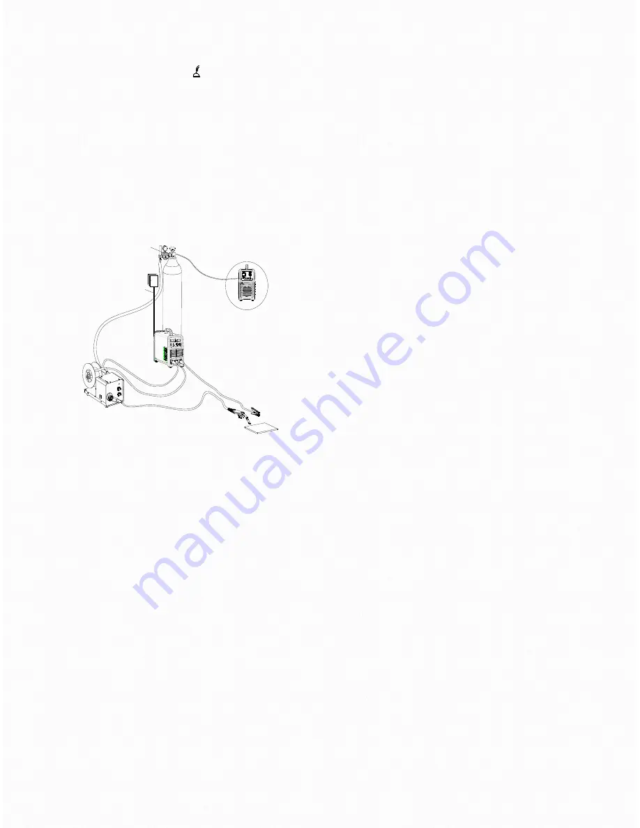
Insert the welding torch into the “ ” output socket on the
front panel of the wire feeder, and tighten it. Manually thread
the welding wire into the torch body.
Insert the quick plug of the interconnection cable set into the
“+” output terminal of the welding machine, and tighten it
clockwise. Connect the other end of the interconnection on
the rear of the wire feed unit
Insert the multi pin plug of the interconnection cable set into
the control cable socket of the welding machine and connect
the other end of the control cable into the rear of the wire
feed unit
Installation of the wire spool
Install the wire spool on the spindle adapter on the wire
feeder, locating the hole on the wire spool to the fixing pin on
the spindle adapter.
Select the correct size feed drive roll according to the size of
welding wire.
Release the pressure arm of the wire feeder to thread the
wire through the guide tube, and into the drive roll groove.
Adjust the pressure arm, ensuring no sliding of the wire. Too
high pressure will lead to wire distortion, which will a
ff
ect
wire feeding.
Press the inch wire feeding button to thread the wire out of
the torch head.
Installation of the cylinder
Connect the cylinder equipped with a regulator to the gas
inlet on the wire feeder with a hose, and tighten it with a
hose clamp.
Please note:
Avoid excessive exposure of the cylinder to high
temperature or sunlight.
Always keep the cylinder in an upright position
Always fix the cylinder securely
Before the installation of gas regulator, open and close the
valve for several times in order to remove the dust on the
joint.
Keep your head and face away from the cylinder valve outlet
when opening the cylinder valve.
Leakage of shield gas a
ff
ects welding performance, so
tighten the cylinder valve joint with a spanner. Check for
leaks
10
Machine rear
Cable of the heater
Gas regulator
Input cable
Cylinder
Wire feeder
Gas hose
Welding torch
Workpiece
Summary of Contents for MIG 250S
Page 16: ...Electrical schematic 7 15...
Page 17: ...Parts list 8 16...


