Essential Charging Station
—
Owner’s Manual
Version F
Essential Charging Station
6
5
H
H
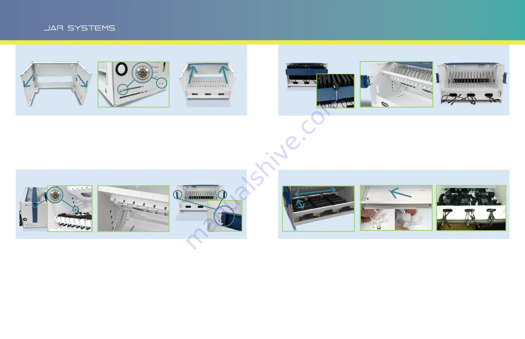
Mount the Tray to the Chassis
H. Pull out the sides of the chassis to the depth
needed for your device. If the sides will not slide
out easily, loosen the pre-installed screws on the
sides. Note: To prevent unauthorized removal
of devices, do not extend the sides further than
needed to fit the devices.
I. Rest the tray on the tabs near the front of the
chassis. Insert 3 [B2] screws with plastic washers
through the chassis and into the tray on each side
of the station.
Install Rubber Bumper (Optional)
J. To protect your devices from hitting the back edge
of the chassis, utilize the supplied rubber bumper.
Install the Top Security Bar (Optional)
K. For security, place the top locking bar at the lowest
height that will fit over the devices. Use 2 [B2]
screws on the top two holes on the outside. Open
the tray lid and prop it up by placing a security
screw or the Torx wrench in the side of the station.
Install 1 [A1] screw from the inside of the chassis to
prevent removal, on both sides.
Insert the Dividers into the Tray
L. Remove the pre-installed divider locks from under
the shelf. Insert the dividers into the slots on the
shelf. Ensure that all dividers are properly seated
and re-install the divider locks beneath the shelf
using 6 [A1] screws.
Install the Front Locking Arms (Optional)
M. For security, install the front locking arms using 2
[A1] screws on each side. Screws for the locking
arms should be installed from the inside of the
chassis to prevent removal.
N. Use the included padlock to secure the station by
looping it through the holes in the arms. Using the
padlock in the “upside down” position may be
easier for some users.
This step completes the
setup for USB-C configurations.
Cable Management
(AC stations only)
O. Open the tray lid and prop it up by placing a
security screw or the Torx wrench in the side of the
station.
P. Determine the length of cable that is needed to reach
from the tray to the devices.
Q. Determine the best method of arranging the cables
that come with your device.
AC ADAPTERS FRONT TO BACK: Best for some
wider adapters.
AC ADAPTERS LEFT TO RIGHT: Best for some
narrower adapters.
TABLET (NO AC ADAPTER): Use provided clips [F6]
beneath shelf to secure cables in groups of 5-6.
TIP: Adapters can often be installed as they come bundled in the
box. If the cables are not bundled at all, twist ties or Velcro
ties are helpful. If the devices have larger AC adapters (5”x
2”x 1.25” or larger) the adapters will fit snugly in the tray.
In this case it may be best to arrange most of the adapters
as far back in the tray as possible from left to right, flipping
about half on their side. Contact JAR Systems for additional
assistance.
R. After AC adapters are arranged in the tray, plug
them into the power strip. For best results, bundle
any excess cable length if it is not already.
S. (OPTIONAL) Secure the tray lid shut using the
security screw and washer that were removed
in step A and the Torx key to prevent adapters
from being removed or tampered with.
This step
completes the setup for AC configurations.
L
L
M
M
N
N
II
JJ
P
P
Q
Q
Q
Q
CONTINUED
CONTINUED
R
R
O
O
K
K
Want to skip this cable management process? CS-1610 and CS-1210 AC charging stations can be upgraded to
Quick-Sense USB-C charging. Contact JAR Systems for more information: 866.393.4202 JAR-Systems.com


