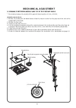


20
CorrECt Condition
stEP and
itEms to
ChECk
05)
PrEssEr
Foot liFtEr
sWitCh
06)
ProCEdurE
dEFECtivE Condition
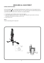
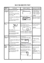
Turn the handwheel toward you.
Lower the needle bar from its
highest to lowest position.
Raise the needle bar from its
lowest position to highest
position.
If the result is correct condition,
press the start/stop button to
proceed the next step.
If the result is defective condition,
press the reverse stitch button to
proceed the next step.
Buzzer does not sound.
Stitch width or length
symbol does not appear.
–rEmEdy–
Replace the circuit board
A.
Replace the circuit board
P.
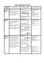
Zigzag motor does not get
default position.
buzzer does not sound.
–rEmEdy–
Replace the zigzag motor.
Replace the circuit board
A.
Feed motor does not get
default position.
buzzer does not sound.
–rEmEdy–
Replace the feed motor.
Replace the circuit board
A.
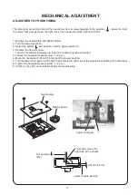
uPPEr shaFt
Positioning
sEnsor
07)
zigzag motor
(stEP motor)
and
FEEd motor
Turn the handwheel toward you.
Lower the needle bar its highest
to position (zigzag phase).
Press the needle up/down button.
Raise the needle bar from its
lowest position to its highest
position (feed phase).
Press the needle up/down button.
If the result is correct condition,
press the start/stop button to
proceed the next step.
If the result is defective condition,
press the reverse stitch button to
proceed the next step.
LCD displays “06”.
Turn the handwheel.
LCD displays stitch width symbol
when the needle bar is at zigzag
phase.
Stitch
width
symbol
Stitch
length
symbol
LCD displays stitch length symbol
when the needle bar is at feed
phase.
LCD displays “07”.
Press the needle up/down button
when LCD displays stitch width
symbol.
The Zigzag motor will be initialized
and get its default position.
Stitch
width
symbol
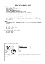
sElF-diagnostiC tEst
Move the presser foot lifter up and
down.
If the result is correct condition,
press the start/stop button to
proceed the next step.
If the result is defective condition,
press the reverse stitch button to
proceed the next step.
LCD displays “05”.
When the presser foot lifer is lowered,
buzzer sounds and LCD displays
presser foot symbol.
When the buttonhole lever is raised,
buzzer sounds and the presser foot
symbol disappears.
Presser
foot
symbol
Buzzer does not sound.
Presser foot symbol does
not appear.
–rEmEdy–
Adjust the presser foot
lifter switch position.
Replace the presser foot
lifter switch.
Replace the circuit board
A.
Press the needle up/down button
when LCD displays stitch length
symbol.
The feed motor will be initialized
and get its default position.
Stitch
length
symbol