77
UMG 509-PRO
www.janitza.com
12.8 Overrange
The overrange message is displayed as long as
the condition is present and it cannot be acknowl-
edged. The measuring range is exceeded if at
least one of the four voltage or current measure-
ment inputs lies outside its specified measuring
range.
Limit values for overrange (200 ms effective val-
ues):
I
=
7.5 Arms
UL-N
=
600 Vrms
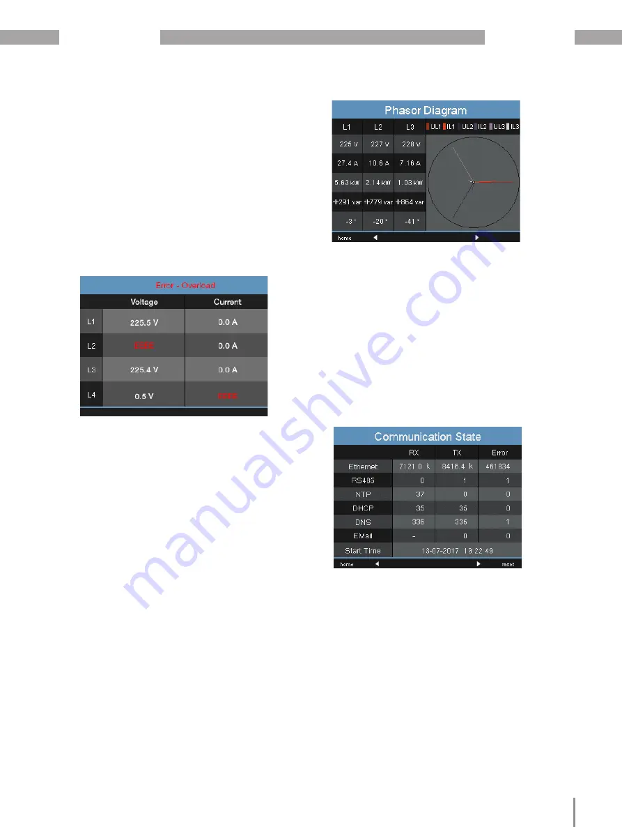
Fig. Display of overrange in voltage circuit L2 and
current path I4
12.9 Control of the power measurement
1.Short-circuit all current transformer outputs
except one.
2.Check the displayed powers.
·The device must only show power in the phase
with the current transformer input that is not
short-circuited.
·If this is not the case, check the connection of
the measured voltage and measured current.
If the amount of active power is correct, but the
sign of the active power is negative, this can have
two causes:
1.The connections S1(k) and S2(l) on the current
transformer are reversed.
2.Active energy is returned to the grid.
Fig. In the phasor diagram, voltages are shown
with long phasors and currents with shorter
phasors.
12.10 Control of the communication
The device counts all received (RX), all sent (TX)
and all faulty data packets.
Ideally, the number of errors displayed in the Error
column is zero.
Pressing button 6 resets the counters for the data
packets to 0. The start time for the new count is
automatically reset.
Fig. Communication status


