


7 / 8
General information
1
2
Janitza electronics GmbH
Vor dem Polstück 6
35633 Lahnau, Germany
Support tel. +49 6441 9642-22
Fax +49 6441 9642-30
E-mail: [email protected]
www.janitza.com
www
.janitza.com
Doc no. 2.100.010.1 05/2018
Item no. 33.03.373
Smart Energy Panel
JPC70
Installation instructions
Installation
Device settings
Deutsche V
ersion:
siehe V
or
derseite
3
2
Safety
Safety instructions
The installation instructions do not include
a complete list of all safety measures necessary
for operating the device.
Special operating conditions may require
additional measures. The installation
instructions contain notes that must be
observed for your personal safety and to
prevent property damage.
ATTENTION
Indicates an imminently dangerous situation
that can result in property damage or
environmental damage in the event of
noncompliance.
NOTE
Points out procedures during which a danger
of injuries or property damage does not exist.
Safety instructions are highlighted by a warning
triangle and are presented as follows depending
on the level of risk:
DANGER
Indicates an imminent danger that will result
in serious and/or fatal injuries.
WARNING
Indicates a potentially dangerous situation
that can result in serious injuries or death.
CAUTION
Indicates a potentially dangerous situation
that can result in minor injuries or property
damage.
Safety measures
When operating electrical devices, specific
parts of these devices inevitably carry
dangerous voltage. As a result, serious bodily
harm or property damage can occur if they are
not handled correctly:
• Before connecting the device, ground it at
the protective conductor terminal if available.
• Dangerous voltages may be present in all
circuit parts connected to the voltage supply.
• There may still be dangerous voltages present
in the device even after it is disconnected
from the supply voltage (capacitor storage).
• Do not exceed the threshold values specified
in the user manual and on the rating
plate. This must also be observed during
inspections and commissioning.
• Observe the safety instructions and warning
notices in the documents that accompany
the devices.
Qualified personnel
To prevent personal injuries and property
damage, only qualified personnel with electrical
engineering training may work on the device.
They must also have knowledge
• Of the national accident prevention
regulations
• In safety technology standards
• In the installation, commissioning and
operation of the device.
Intended use
The device is
• intended for installation in switching cabinets
and small installation distributors. Refer
to the technical data for the installation
location.
• not intended for installation in vehicles! Using
the device in mobile equipment is considered
an unusual environmental condition and is
only permissible by special agreement.
• not intended for installation in areas exposed
to harmful oils, acids, gases, vapors, dust
and radiation, etc.
The prerequisites for smooth and safe operation
of the device include proper transport, storage,
setup and assembly, as well as proper operation
and maintenance.
DANGER
Electrical voltage!
It may result in serious bodily harm or death
due to:
• Touching live exposed or stripped cores.
• Device inputs that are dangerous to touch.
Before starting work, disconnect your
system from the power supply.
Verify that there is no current.
• Cut-out size: 186.8 ±1 mm x 129.8 ±1 mm
• Wall thickness: 2 to 6 mm
Assembly
User manual:
Disclaimer
It is essential that the information products
for the devices are observed to ensure
safe operation and achieve the specified
performance characteristics and product
features. Janitza electronics GmbH assumes
no liability for personal injuries, property
damage and financial losses resulting from the
failure to observe the information products.
Make sure that your information products are
legible and accessible.
You can find more documentation on our web
site www.janitza.de under Support > Downloads.
Copyright notice
© 2018 - Janitza electronics GmbH - Lahnau.
All rights reserved. Any duplication, processing,
distribution and any other kind of use, even in
part, is prohibited.
Subject to technical changes.
• Make sure that the installation instructions
match your device.
• First, make sure you have read and
understood the document accompanying
the product.
• Keep the documents accompanying the
product accessible through its service life
and hand them over to the subsequent
owner where applicable.
• Refer to www.janitza.de for information
concerning device revisions and
the associated adjustments to the
documentation accompanying the product.
Disposal
Please observe the national regulations.
Dispose of individual parts, where necessary,
depending on the properties and existing
country-specific regulations, e.g. as:
• Electronic waste
• Plastic
• Metal
or commission a certified disposal company
with the scrapping.
Relevant laws,
applied standards and directives
Please refer to the Declaration of Conformity
on our web site (www.janitza.de) for the laws,
standards and directives applied by Janitza
electronics GmbH.
CAUTION
Property damage due to noncompliance
with the assembly instructions.
Noncompliance with the assembly instructions
can damage or destroy your device.
Ensure sufficient air circulation in your
installation environment and, where
applicable, sufficient cooling with high
ambient temperatures. Follow the general
ESD protective measures.
NOTE
You can find more detailed information about
the device functions, data and assembly in the
user manual.
Fig. 1: Installation position, side view JPC70
Fig. 2: Installation position, side distances JPC70
Torque: 0.6 Nm.
The device must be installed using the supplied
retaining clamps (see Fig. 06) on a level, clean and
burr-free surface. Unevenness can cause damage
to the display and result in the penetration of dust
and water.
1. Insert the front side of the device in the
provided installation cut-out.
2. Insert the retaining clamps in the recesses
provided on the device.
Fig. 3: Inserting the retaining clamps
3. Slide the retaining clamps towards the rear until
they are flush with the back side of the recess.
Fig. 4: Sliding the retaining clamps towards the rear
4. Fix the retaining clamps by tightening
the fastening screws on the wall and/or
the switch cabinet sheet metal.
Fig. 5: Fixing the retaining clamps
Fig. 6: Rear view with retaining clamps
The stand-by screen with the Janitza logo
appears after the device has been activated
for the first time. Touch the screen to call up the
start-up screen.
Fig. 11: JPC70 start-up screen
You must be logged in as an administrator to
make configurations on the device.
1. Touch the display of the current role in the
status bar to open the login mask. After a
restart of the system, this is the
ViewOnly
role.
2. Enter login data for the administrator in the
user and password input fields. (the factory
setting for both of these fields is "Admin")
Faults are discharged effectively via a
grounding lug. The cable shield (e.g. Ethernet)
is discharged via the ground plate.
5
Connecting elements and diagnostic LEDs
4
Device connection
Ground conductor:
The connection to the ground potential must
be made as short as possible and adequately
strong (≥4 mm²) via the provided flat plug
connection (Faston 6.3 mm).
2
Unshielded conductors:
All unshielded conductors must be relieved of
tensile stress with cable ties on the ground plate.
1
LED
Color
Description
RDY/F
Yellow BOOT, SERVICE or DIAGNOSIS
mode
R/E
Green
RUN mode: Application running.
Red
BOOT, SERVICE or DIAGNOSIS
mode
Button code
Mode
Description
Press the button briefly (<2 s)
RUN
A hardware reset is initiated:
• All user programs are stopped.
• Outputs of all connected
modules are set to zero.
Then the device starts up in
RUN mode and the application
is started.
Press and hold the button (>2 s)
DIAGNOSIS Only for internal use.
1. Press the button briefly (<2 s)
2. Pause (<2 s)
3. Press and hold the button (>2 s)
BOOT
Only for internal use.
7
CAUTION
Property damage due to noncompli-
ance of the connection conditions or
impermissible voltage swells!
Noncompliance of the connection
conditions or exceeding the permissible
voltage range can damage or destroy
your device.
Before you connect the device to the
supply voltage, please observe the
following:
•
In building installations, secure the
supply voltage with a UL/IEC-listed
circuit breaker/fuse.
•
The circuit breaker
-
must be easily accessible for the
user and located in the vicinity of
the device.
-
must be labeled for the respec-
tive device.
6
1
2
3
4
5
6
7
8
9
1
LED CAN-bus status
6
USB Interface
2
LED: R/E
7
Ethernet interface
3
LED: RDY/F
8
Reset button
4
24V supply voltage
9
CAN-bus interface
(internal)
5
Ground lug
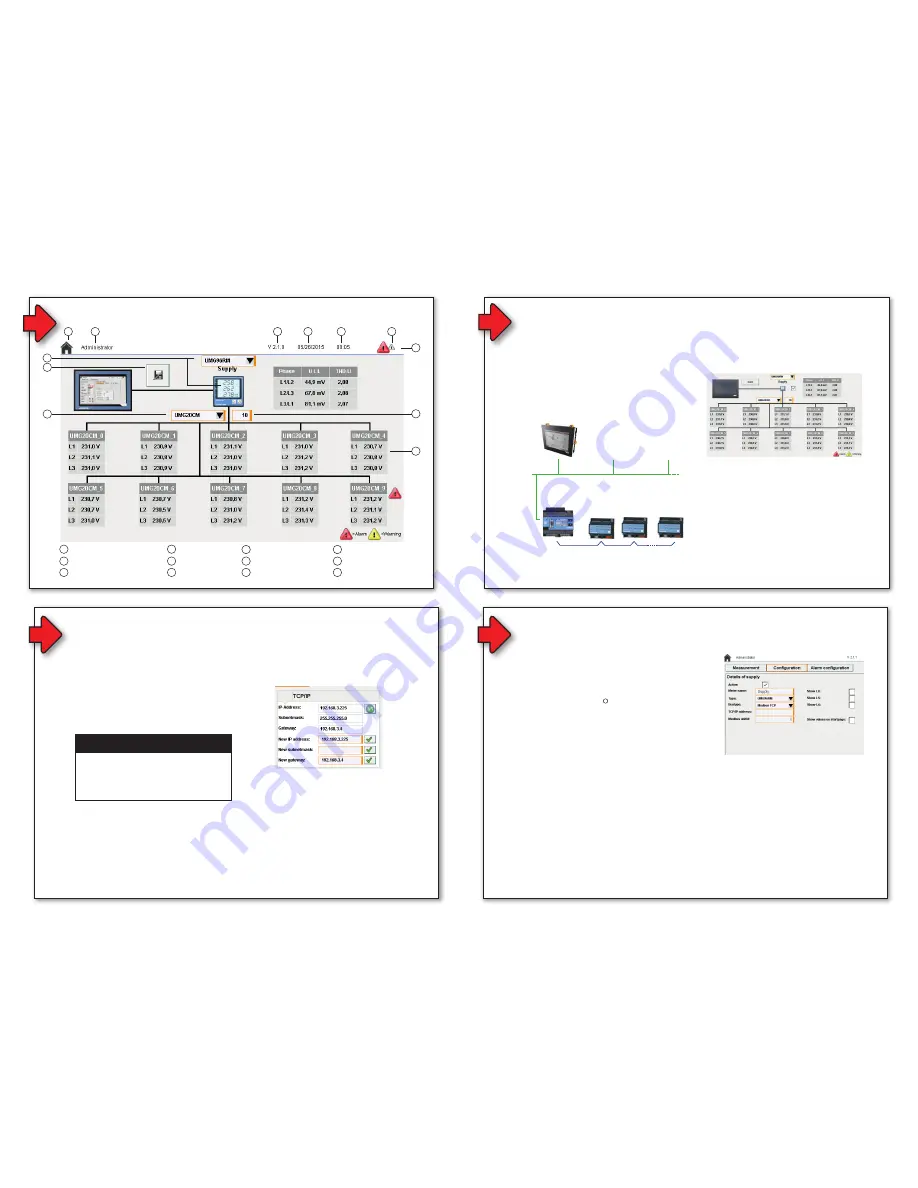
Start screen
1
Selected slave devices
6
Software version
2
Save
button
3
Selected master device
4
Home
button
7
Current date
8
Current time
9
Warnings/alarms
10
Status bar
11
Number of slave devices
12
Slave device (tabular
representation)
5
Active user role
Configuration
2
1
Fig. 7: Rear view - JPC70 with connections
Fig. 8: Rear view - JPC70 connections and LEDs
1
2
3
5
4
6
7
8
9
11
12
10
Fig. 9: JPC70 start-up screen (topology view)
The JPC70 is connected via the Ethernet
interface to a master device in a bus system
in order to be able to manage this bus system
on the JPC70. Refer to the documentation for
the respective master and slave devices for the
configuration of a bus system.
Connect the JPC70 and master device via the
Ethernet interfaces.
JPC70
UMG 605-PRO
as a master
Slave 1
Slave 2
Slave n
Ethernet
Modbus
Modbus
Modbus
Ethernet
Fig. 10: Topology view of a bus system
DANGER
The ground potential (ground lug on the device)
and GND connection of the voltage supply are
connected internally in this device.
Use at least one PELV power supply unit.
The factory settings must be accepted after the
initial commissioning. For this purpose, proceed
as follows:
1. Touch the display of version, date or time
to open the system settings.
2. Press the
ACK
button.
• The standard IP address and gateway are
loaded to the TCP/IP settings.
NOTE
Performing TCP/IP configuration first
is recommended, because assignment
of a fixed IP address without consulting
with the network administrator can result
in complications.
3. Enter an IP address and the corresponding
gateway address under in the
New IP
address
New gateway
text input fields
under
TCP/IP
.
4. Confirm the new address by pressing
the button with the green check mark.
5. Update the view of the IP configuration
by pressing the
Update
button next to the
IP address
text input field.
6. Press the
Save
button to save the settings.
Fig. 12: TCP-IP configuration of the JPC70
Integrating the master device:
8
9
Network settings
Show bus system
1. Log in as an administrator. (See
Step 7
)
2. Navigate back to the start-up screen
by pressing the
Home
button.
3. Open the settings of the master device by
pressing the illustration of a UMG master
device (see Fig. 09
3
).
4. Select the type of the master device
from the
Type
selection list.
5. Select the option Modbus TCP in the
Bus type
selection list.
6. Enter the IP address of the master device
in the
TCP/IP address
text input field.
7. Enter the Modbus address of the master
device in the
Modbus UnitID
text input
field.
8. You can optionally have the values of the
master device displayed on the start-up
screen. For this purpose, activate the
Show values on startpage selection box.
9. Save the settings by pressing the Save
button.
• Proceed with the configuration of the slave
devices.
Fig. 13: Master device configuration
10
General information
Net weight
600 g
Dimensions
197 mm x 140 mm x 47.8 mm
Backlight (LED)
• Brightness: type 500 cd/m
2
• Half brightness time
1)
: 50,000 h
Cooling
Passive
Power button
No
Reset button
Yes
Status display (7 LEDs)
• Supply voltage OK
• Operating status
• Module status
• Ethernet
Processor
ARM Cortex-A8, 1 GHz
Working memory
256 Mbyte DDRAM
Interfaces
USB
2 x USB 2.0 type A rating 0.49 A
Ethernet
• 1x RJ45 shielded
• Max. transmission rate 10/100 Mbit/s
• Cable type: 10BASE-T/100BASE-TX
Ambient conditions
Protection rating according
to EN 60529
IP65 front side, IP20 rear side
Installation elevation above
sea level
0 to 2000 m
Operating temperature
-20 to 60 °C
Storage and transport
temperature
-20 to 70 °C
Air humidity
5 to 96 %, non-condensing
Electrical properties
Supply voltage
24 V DC -15% / +20%
Max. power consumption
2)
6.2 W
Pole reversal protection
Yes
Display
Type
Color TFT
Diagonal
7"
Colors
16.7 million (RGB, 8 bits per channel)
Resolution
WVGA, 800 x 480 pixels
Contrast
typically 600:1
Touchscreen
Yes
Technical data
1) With 25°C ambient temperature. Reduction of brightness
by 50% can increase the half brightness time by about 50%.
2) Without USB interfaces
Integrating slave devices:
1. Switch to the start-up screen.
• The message "Reboot necessary!" appears
after configuration of the master device.
2. Select the appropriate slave device type
from the selection list.
3. Enter the number of slave devices
connected in the bus in the input field next
to the selection list.
4. Now open the configuration for the
respective slave device by touching the
corresponding tabular representation.
5. Enter the Modbus address of the device
in the
Modbus address
input field.
6. Save the settings by pressing the
Save
button.
7. Repeat steps 4-6 for all slave devices
in the bus system.
8. Navigate back to the start-up screen.
9. Save the setting by pressing the
Save
button.
Communication between the master device
and JPC70 takes place via the Modbus TCP
protocol and must be started explicitly:
1. Log in as an administrator.
2. Navigate to the system settings.
3. Activate the selection box if you want
to overwrite the configuration of the
connected devices with the configuration
from the JPC70.
4. Press the start button under
Modbus TCP
.
• The update symbol appears next to the
Modbus TCP
menu item and displays an
active transmission.
Finishing the configuration
The device must be restarted to finish the
configuration:
1. Navigate to the system settings.
2. Press the
Reboot
button under
Device
.
• At this point, you have the opportunity to
save the settings.
NOTE
If the device remains in SERVICE mode
during the restart, disconnect the device
supply voltage and re-connect it after about
2 seconds.
Activating communication via Modbus TCP
Fig. 14: Slave device configuration
Fig. 15: Modbus TCP system settings
General information
1
2
Janitza electronics GmbH
Vor dem Polstück 6
35633 Lahnau, Germany
Support tel. +49 6441 9642-22
Fax +49 6441 9642-30
E-mail: [email protected]
www.janitza.com
www
.janitza.com
Doc no. 2.100.010.1 05/2018
Item no. 33.03.373
Smart Energy Panel
JPC70
Installation instructions
Installation
Device settings
Deutsche V
ersion:
siehe V
or
derseite
3
2
Safety
Safety instructions
The installation instructions do not include
a complete list of all safety measures necessary
for operating the device.
Special operating conditions may require
additional measures. The installation
instructions contain notes that must be
observed for your personal safety and to
prevent property damage.
ATTENTION
Indicates an imminently dangerous situation
that can result in property damage or
environmental damage in the event of
noncompliance.
NOTE
Points out procedures during which a danger
of injuries or property damage does not exist.
Safety instructions are highlighted by a warning
triangle and are presented as follows depending
on the level of risk:
DANGER
Indicates an imminent danger that will result
in serious and/or fatal injuries.
WARNING
Indicates a potentially dangerous situation
that can result in serious injuries or death.
CAUTION
Indicates a potentially dangerous situation
that can result in minor injuries or property
damage.
Safety measures
When operating electrical devices, specific
parts of these devices inevitably carry
dangerous voltage. As a result, serious bodily
harm or property damage can occur if they are
not handled correctly:
• Before connecting the device, ground it at
the protective conductor terminal if available.
• Dangerous voltages may be present in all
circuit parts connected to the voltage supply.
• There may still be dangerous voltages present
in the device even after it is disconnected
from the supply voltage (capacitor storage).
• Do not exceed the threshold values specified
in the user manual and on the rating
plate. This must also be observed during
inspections and commissioning.
• Observe the safety instructions and warning
notices in the documents that accompany
the devices.
Qualified personnel
To prevent personal injuries and property
damage, only qualified personnel with electrical
engineering training may work on the device.
They must also have knowledge
• Of the national accident prevention
regulations
• In safety technology standards
• In the installation, commissioning and
operation of the device.
Intended use
The device is
• intended for installation in switching cabinets
and small installation distributors. Refer
to the technical data for the installation
location.
• not intended for installation in vehicles! Using
the device in mobile equipment is considered
an unusual environmental condition and is
only permissible by special agreement.
• not intended for installation in areas exposed
to harmful oils, acids, gases, vapors, dust
and radiation, etc.
The prerequisites for smooth and safe operation
of the device include proper transport, storage,
setup and assembly, as well as proper operation
and maintenance.
DANGER
Electrical voltage!
It may result in serious bodily harm or death
due to:
• Touching live exposed or stripped cores.
• Device inputs that are dangerous to touch.
Before starting work, disconnect your
system from the power supply.
Verify that there is no current.
• Cut-out size: 186.8 ±1 mm x 129.8 ±1 mm
• Wall thickness: 2 to 6 mm
Assembly
User manual:
Disclaimer
It is essential that the information products
for the devices are observed to ensure
safe operation and achieve the specified
performance characteristics and product
features. Janitza electronics GmbH assumes
no liability for personal injuries, property
damage and financial losses resulting from the
failure to observe the information products.
Make sure that your information products are
legible and accessible.
You can find more documentation on our web
site www.janitza.de under Support > Downloads.
Copyright notice
© 2018 - Janitza electronics GmbH - Lahnau.
All rights reserved. Any duplication, processing,
distribution and any other kind of use, even in
part, is prohibited.
Subject to technical changes.
• Make sure that the installation instructions
match your device.
• First, make sure you have read and
understood the document accompanying
the product.
• Keep the documents accompanying the
product accessible through its service life
and hand them over to the subsequent
owner where applicable.
• Refer to www.janitza.de for information
concerning device revisions and
the associated adjustments to the
documentation accompanying the product.
Disposal
Please observe the national regulations.
Dispose of individual parts, where necessary,
depending on the properties and existing
country-specific regulations, e.g. as:
• Electronic waste
• Plastic
• Metal
or commission a certified disposal company
with the scrapping.
Relevant laws,
applied standards and directives
Please refer to the Declaration of Conformity
on our web site (www.janitza.de) for the laws,
standards and directives applied by Janitza
electronics GmbH.
CAUTION
Property damage due to noncompliance
with the assembly instructions.
Noncompliance with the assembly instructions
can damage or destroy your device.
Ensure sufficient air circulation in your
installation environment and, where
applicable, sufficient cooling with high
ambient temperatures. Follow the general
ESD protective measures.
NOTE
You can find more detailed information about
the device functions, data and assembly in the
user manual.
Fig. 1: Installation position, side view JPC70
Fig. 2: Installation position, side distances JPC70
Torque: 0.6 Nm.
The device must be installed using the supplied
retaining clamps (see Fig. 06) on a level, clean and
burr-free surface. Unevenness can cause damage
to the display and result in the penetration of dust
and water.
1. Insert the front side of the device in the
provided installation cut-out.
2. Insert the retaining clamps in the recesses
provided on the device.
Fig. 3: Inserting the retaining clamps
3. Slide the retaining clamps towards the rear until
they are flush with the back side of the recess.
Fig. 4: Sliding the retaining clamps towards the rear
4. Fix the retaining clamps by tightening
the fastening screws on the wall and/or
the switch cabinet sheet metal.
Fig. 5: Fixing the retaining clamps
Fig. 6: Rear view with retaining clamps
The stand-by screen with the Janitza logo
appears after the device has been activated
for the first time. Touch the screen to call up the
start-up screen.
Fig. 11: JPC70 start-up screen
You must be logged in as an administrator to
make configurations on the device.
1. Touch the display of the current role in the
status bar to open the login mask. After a
restart of the system, this is the
ViewOnly
role.
2. Enter login data for the administrator in the
user and password input fields. (the factory
setting for both of these fields is "Admin")
Faults are discharged effectively via a
grounding lug. The cable shield (e.g. Ethernet)
is discharged via the ground plate.
5
Connecting elements and diagnostic LEDs
4
Device connection
Ground conductor:
The connection to the ground potential must
be made as short as possible and adequately
strong (≥4 mm²) via the provided flat plug
connection (Faston 6.3 mm).
2
Unshielded conductors:
All unshielded conductors must be relieved of
tensile stress with cable ties on the ground plate.
1
LED
Color
Description
RDY/F
Yellow BOOT, SERVICE or DIAGNOSIS
mode
R/E
Green
RUN mode: Application running.
Red
BOOT, SERVICE or DIAGNOSIS
mode
Button code
Mode
Description
Press the button briefly (<2 s)
RUN
A hardware reset is initiated:
• All user programs are stopped.
• Outputs of all connected
modules are set to zero.
Then the device starts up in
RUN mode and the application
is started.
Press and hold the button (>2 s)
DIAGNOSIS Only for internal use.
1. Press the button briefly (<2 s)
2. Pause (<2 s)
3. Press and hold the button (>2 s)
BOOT
Only for internal use.
7
CAUTION
Property damage due to noncompli-
ance of the connection conditions or
impermissible voltage swells!
Noncompliance of the connection
conditions or exceeding the permissible
voltage range can damage or destroy
your device.
Before you connect the device to the
supply voltage, please observe the
following:
•
In building installations, secure the
supply voltage with a UL/IEC-listed
circuit breaker/fuse.
•
The circuit breaker
-
must be easily accessible for the
user and located in the vicinity of
the device.
-
must be labeled for the respec-
tive device.
6
1
2
3
4
5
6
7
8
9
1
LED CAN-bus status
6
USB Interface
2
LED: R/E
7
Ethernet interface
3
LED: RDY/F
8
Reset button
4
24V supply voltage
9
CAN-bus interface
(internal)
5
Ground lug
Start screen
1
Selected slave devices
6
Software version
2
Save
button
3
Selected master device
4
Home
button
7
Current date
8
Current time
9
Warnings/alarms
10
Status bar
11
Number of slave devices
12
Slave device (tabular
representation)
5
Active user role
Configuration
2
1
Fig. 7: Rear view - JPC70 with connections
Fig. 8: Rear view - JPC70 connections and LEDs
1
2
3
5
4
6
7
8
9
11
12
10
Fig. 9: JPC70 start-up screen (topology view)
The JPC70 is connected via the Ethernet
interface to a master device in a bus system
in order to be able to manage this bus system
on the JPC70. Refer to the documentation for
the respective master and slave devices for the
configuration of a bus system.
Connect the JPC70 and master device via the
Ethernet interfaces.
JPC70
UMG 605-PRO
as a master
Slave 1
Slave 2
Slave n
Ethernet
Modbus
Modbus
Modbus
Ethernet
Fig. 10: Topology view of a bus system
DANGER
The ground potential (ground lug on the device)
and GND connection of the voltage supply are
connected internally in this device.
Use at least one PELV power supply unit.
The factory settings must be accepted after the
initial commissioning. For this purpose, proceed
as follows:
1. Touch the display of version, date or time
to open the system settings.
2. Press the
ACK
button.
• The standard IP address and gateway are
loaded to the TCP/IP settings.
NOTE
Performing TCP/IP configuration first
is recommended, because assignment
of a fixed IP address without consulting
with the network administrator can result
in complications.
3. Enter an IP address and the corresponding
gateway address under in the
New IP
address
New gateway
text input fields
under
TCP/IP
.
4. Confirm the new address by pressing
the button with the green check mark.
5. Update the view of the IP configuration
by pressing the
Update
button next to the
IP address
text input field.
6. Press the
Save
button to save the settings.
Fig. 12: TCP-IP configuration of the JPC70
Integrating the master device:
8
9
Network settings
Show bus system
1. Log in as an administrator. (See
Step 7
)
2. Navigate back to the start-up screen
by pressing the
Home
button.
3. Open the settings of the master device by
pressing the illustration of a UMG master
device (see Fig. 09
3
).
4. Select the type of the master device
from the
Type
selection list.
5. Select the option Modbus TCP in the
Bus type
selection list.
6. Enter the IP address of the master device
in the
TCP/IP address
text input field.
7. Enter the Modbus address of the master
device in the
Modbus UnitID
text input
field.
8. You can optionally have the values of the
master device displayed on the start-up
screen. For this purpose, activate the
Show values on startpage selection box.
9. Save the settings by pressing the Save
button.
• Proceed with the configuration of the slave
devices.
Fig. 13: Master device configuration
10
General information
Net weight
600 g
Dimensions
197 mm x 140 mm x 47.8 mm
Backlight (LED)
• Brightness: type 500 cd/m
2
• Half brightness time
1)
: 50,000 h
Cooling
Passive
Power button
No
Reset button
Yes
Status display (7 LEDs)
• Supply voltage OK
• Operating status
• Module status
• Ethernet
Processor
ARM Cortex-A8, 1 GHz
Working memory
256 Mbyte DDRAM
Interfaces
USB
2 x USB 2.0 type A rating 0.49 A
Ethernet
• 1x RJ45 shielded
• Max. transmission rate 10/100 Mbit/s
• Cable type: 10BASE-T/100BASE-TX
Ambient conditions
Protection rating according
to EN 60529
IP65 front side, IP20 rear side
Installation elevation above
sea level
0 to 2000 m
Operating temperature
-20 to 60 °C
Storage and transport
temperature
-20 to 70 °C
Air humidity
5 to 96 %, non-condensing
Electrical properties
Supply voltage
24 V DC -15% / +20%
Max. power consumption
2)
6.2 W
Pole reversal protection
Yes
Display
Type
Color TFT
Diagonal
7"
Colors
16.7 million (RGB, 8 bits per channel)
Resolution
WVGA, 800 x 480 pixels
Contrast
typically 600:1
Touchscreen
Yes
Technical data
1) With 25°C ambient temperature. Reduction of brightness
by 50% can increase the half brightness time by about 50%.
2) Without USB interfaces
Integrating slave devices:
1. Switch to the start-up screen.
• The message "Reboot necessary!" appears
after configuration of the master device.
2. Select the appropriate slave device type
from the selection list.
3. Enter the number of slave devices
connected in the bus in the input field next
to the selection list.
4. Now open the configuration for the
respective slave device by touching the
corresponding tabular representation.
5. Enter the Modbus address of the device
in the
Modbus address
input field.
6. Save the settings by pressing the
Save
button.
7. Repeat steps 4-6 for all slave devices
in the bus system.
8. Navigate back to the start-up screen.
9. Save the setting by pressing the
Save
button.
Communication between the master device
and JPC70 takes place via the Modbus TCP
protocol and must be started explicitly:
1. Log in as an administrator.
2. Navigate to the system settings.
3. Activate the selection box if you want
to overwrite the configuration of the
connected devices with the configuration
from the JPC70.
4. Press the start button under
Modbus TCP
.
• The update symbol appears next to the
Modbus TCP
menu item and displays an
active transmission.
Finishing the configuration
The device must be restarted to finish the
configuration:
1. Navigate to the system settings.
2. Press the
Reboot
button under
Device
.
• At this point, you have the opportunity to
save the settings.
NOTE
If the device remains in SERVICE mode
during the restart, disconnect the device
supply voltage and re-connect it after about
2 seconds.
Activating communication via Modbus TCP
Fig. 14: Slave device configuration
Fig. 15: Modbus TCP system settings


