Busbar tap-off unit
www.janitza.de
60
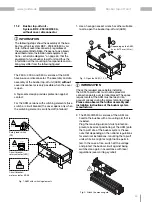
10.13 Installation and equipment options –
schematic diagrams
When changing from variant 1 to variant 2, the
measurement device can be pulled out of the hold-
er, rotated by 180° and reinserted.
N
L1
L2
L3
PE
N
+
-
-
L
INFORMATION
The schematic representations of the installations
show examples! The actual installation/equipment
depends on the busbar tap-off unit variant selected.
Fig.: Variant 1 (AKM 96RM-E-125) with PE connection "below":
The enclosure is mounted in the as-delivered condition.


