Page 16
Legacy
™
Model LRZM Pool/Spa Heater Installation and Operation Manual
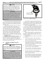
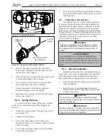
slotted cap is a slotted plastic screw which increases
the manifold pressure when turned clockwise and
decreases the manifold pressure when turned counter-
clockwise.
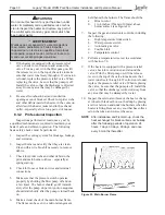
After measurements, and adjustments if neces-
sary, have been made, make sure to replace the 1/8"
NPT plug on the manifold pressure ports, and the
cap on the manifold pressure adjustment screw. It
is extremely important to replace these parts before
leaving the installation. Failure to do so can result in
damage to property or injury or death.
With the heater
fi
ring
, the pressure must be
within the range shown in Table 5. Also check the
pressure with the heater off.
4.3
Special Precautions for LP Gas
LP Gas is heavier than air and can therefore more
readily collect or “pool” in enclosed areas if provision
for proper ventilation is not made. Installation of pool
heaters in enclosed areas such as pits is not recom-
mended. However, if such an installation is required
be sure to pay special attention to proper ventilation
requirements for LP gas. Locate heaters a safe distance
from LP gas cylinders and
fi
lling equipment. Consult
the National Fuel Gas Code (NFPA 54 / ANSI Z223.1,
latest edition), the Natural Gas and Propane Instal-
lation Code in Canada (CAN/CSA B149.1, latest
edition), and any other local codes and
fi
re protection
authorities about speci
fi
c installation restrictions in
your area.
Section 5. Water Connections
5.1 Water
Piping
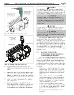
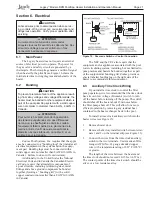
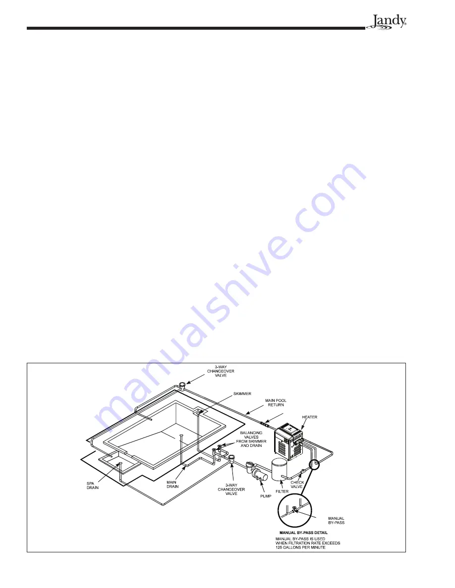
Figure 7 illustrates typical piping for pool equip-
ment in pool/spa combination pools.
For normal installations, do not install a shutoff
valve or any kind of variable restriction in the water
piping between the heater outlet and the pool/spa. In
special installations where a shut-off valve, diverter
valve or other variable restriction is required in the
plumbing between the heater outlet and the pool,
Zodiac Pool Systems, Inc. recommends the installation
of a pressure relief valve on the heater (see Section
5.6).
Arrangement of pool system components other
than as illustrated in these diagrams can affect the
operation of the heater’s water pressure switch.
Location of the heater above or below the pool water
surface can also affect operation of the switch. In
general, the pressure switch can be adjusted to accom-
modate this effect if the heater water connections are
no more than six (6) feet below the pool water surface
and no more than 15 feet above it. See instructions for
pressure switch adjustment (Section 7.5) in the heater
start-up section of this manual for more information
about this.
Note that when pool equipment is located below
the pool surface a leak can result in large scale water
loss or
fl
ooding. Zodiac Pool Systems, Inc. cannot
be responsible for such water loss or
fl
ooding or the
damage caused by it.
For special installations such as water connec-
tions below the water level of the pool, or for other
questions contact the Zodiac Technical Service depart-
ment at (800) 822-7933.
AQUAPURE
Figure 7. Typical Piping Installation
Summary of Contents for Legacy LRZM
Page 2: ......


