background image

- 12 -

 AMD Series                                                                                                 User's Manual

3.3 JBIOSSLC Jumper (Optional)

    The mainboard can support dual BIOS function, please adjust BIOS jumper to 2~3 while 

    USER_BIOS boot failure, then pc will be boot from BAK_BIOS, download the correctly BIOS 

    in our website or save a new BIOS under dos model by BIOS flash tools, then adjust 

    JBIOSSLC jumper to 1~2pin for repair USER_BIOS by BIOS tools.

    PC will be boot from BAK_BIOS while USER_BIOS can't boot under Dual_BIOS model, but it 

    will not to repair USER_BIOS. Suggest to use USER_BIOS model.

JBIOSSLC

NC

  Auto

1-2

  USR_BIOS

2-3

  BAK_BIOS

     NC

  AUTO

           Note: JBIOSSLC for your reference.   

           Please define jumper of mainboard if you use 

           JBIOSSLC jumper.

3.4 IR Connection Header & JDVI_HDMI Jumper&JHPD Jumper

   Connect the IrDA cable (if available) to this IR connector.

   While JDVI_HDMI jumper be shorted #pin 1-2, it will auto detect  DVI device,  if JDVI_HDMI   

   jumper be shorted #pin 2-3,it will work at HDMI.

Pin No.

Definition

1

   VCC

2

   NC

3

   IRRX

4

   GND

5

   IRTX

Pin No.

Definition

Pin1-2    DVI
Pin2-3    HDMI

   JDVI_HDMI Jumper

Pin No.

Definition

Pin1-2    Auto
Pin2-3    HDMI/DVI EN

   JHPD Jumper

    While JHPD jumper is being shorted at pin#1-2, it will 

    automatically detect the HDMI or DVI device connected, 

    however, when certain DVI or HDMI devices can't be 

    detected, please short the jumper to pin #2-3 to manually 

    override the setting.

IRDA

Summary of Contents for JW-A880GMT-EXTREME

Page 1: ...JW A880GMT EXTREME Socket AM3 Processor Mainboard User s Manual Rev 1 0 April 2010 Motherboard Website http www jwele com...

Page 2: ...uarantee the accuracy of the contents This manual is purely technical documentation without any hint or other meanings and we won t commit users misunderstanding of the typesetting error Our products...

Page 3: ...JBIOSSLC Jumper Optional 12 3 4 IR Connection Header JDVI_HDMI Jumper JHPD Jumper 12 3 5 CD_IN Headers JHDT Jumperr 13 3 6 1394 Headers 13 3 7 FAN Power Connectors 14 3 8 Front Panel Switches Speaker...

Page 4: ...ies if there is any broken or part missing please contact with your franchiser IDE Cable X 1 Rear I O Panel X 1 User s Manual X 1 Driver Utility CD X 1 1394 USB bracket X 1 optional SATA power cable X...

Page 5: ...l 1 x RJ45 port 6 x USB 2 0 ports USB 1 1 is compliant 6 x Audio ports Line In Line Out MIC In Rear Speaker Out Center Subwoofer Speaker Out Side Speaker Out Internal I O Connectors 1 x 24 pin ATX mai...

Page 6: ...AMD Series User s Manual 1 3 Mainboard Layout This picture is only for reference...

Page 7: ...ace the meter perhaps other may take along the type equipment USB Connects to USB devices such as scanner digital speakers monitor mouse keyboard hub digital camera joystick etc LAN Connects to Local...

Page 8: ...the holes line up and there are screw holes you can attach the board with studs If the holes line up and there are only slots you can only attach with spacers Take the tip of the spacers and insert th...

Page 9: ...in accordance with the processor specifications It is not recommended that the system bus frequency be set beyond hardware specifications since it does not meet the required standards for the periphe...

Page 10: ...DIMM modules of the same type and size on slots DIMM1 DIMM2 and another 2 DIMM modules of the same type and size on slots DIMM3 DIMM4 To install system memory 1 Power off the computer and unplug the A...

Page 11: ...IE1 Install PCI card into slots PCI1 or PCI2 Each of the IDE port connects up to two IDE drives at Ultra ATA 133 100 66 33 mode by one 40 pin 80 conductor and 3 connector Ultra ATA 66 ribbon cables Co...

Page 12: ...ou are unable to boot up the system because the CPU ratio clock was incorrectly set in the BIOS menu or d whenever there is modification on the CPU or memory modules This header uses a jumper cap to c...

Page 13: ...OS NC AUTO Note JBIOSSLC for your reference Please define jumper of mainboard if you use JBIOSSLC jumper 3 4 IR Connection Header JDVI_HDMI Jumper JHPD Jumper Connect the IrDA cable if available to th...

Page 14: ...D_IN Headers JHDT Jumper Pin Pin Assignment Pin Pin Assignment 1 TA 2 TA 3 GND 4 GND 5 TB 6 TB 7 12V 8 12V 9 10 NC Pin Pin Assignment Pin Pin Assignment 1 CD_L 2 GND 3 GND 4 CD_R 1 2 Default Normal HD...

Page 15: ...is reset switch This connector connects to the case mounted reset switch for rebooting your computer without having to turn off your power switch This is a preferred method of rebooting in order to pr...

Page 16: ...aders 3 10 Front Panel Audio Pin No Header HD Audio Definition AC97 Audio Definition 1 PORT1L Microphone_Left Microphone 2 AGND Ground Ground 3 PORT1R Microphone_Right MIC Power 4 PRESENCE ACZ_DET N A...

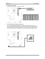
Page 17: ...module 3 12 S PDIF Output Connection Header S PDIF Sony Philips Digital Interface is a standard audio transfer file format It is usually found on digital audio equipment such as a DAT Digital Audio Ta...

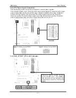
Page 18: ...the plug of the power supply is inserted in the proper orientation and the pins are aligned Then push down the power supply firmly into the connector Your may use the 20 pin ATX power supply as you l...

Page 19: ...ecial features on or off etc 3 Enhancing your computer s behavior For example speeding up performance by turning on shadowing or cache 4 2 To Run BIOS Setup First access BIOS setup menu by pressing F1...

Page 20: ...ted item Please check the following table for the function description of each control key Press F1 to Run SETUP In order to increase system stability and performance our engineering staff is constant...

Page 21: ...Port6 USB Device Not Detected Not Detected Hard Disk Not Detected Not Detected Not Detected Not Detected Not Detected v02 61 C Copyright 1985 2006 American Megatrends Inc BIOS SETUP UTILITY Main Syst...

Page 22: ...LBA Mode Supported Block Mode 16Sectors PIO Mode 4 Async DMA MultiWord DMA 2 Ultra DMA Ultra DMA 6 S M A R T Supported LBA Large Mode Block Multi Sector Transfer PIO Mode DMA Mode S M A R T 32Bit Dat...

Page 23: ...r USB2 1 1 Controller USB2 2 1 Controller USB3 1 1 Controller Enabled HiSpeed Enabled Enabled Enabled Enabled Enabled Enabled v02 61 C Copyright 1985 2006 American Megatrends Inc Legacy USB Support En...

Page 24: ...ogical Count 4 This option should remain disabled for the normal operation The driver developer may enable it for testing purpose Select Screen Select Item Change Option F1 General Help F10 Save and E...

Page 25: ...Disable Disable Above 4G Enable Auto PCI GFXO GPP PCIE1 Gen2 High Speed Mode Disabled v02 61 C Copyright 1985 2006 American Megatrends Inc Options SouthBridge Configuration Click Enter key to enter i...

Page 26: ...v02 61 C Copyright 1985 2006 American Megatrends Inc These options allow you to Enabled Disabled for Floppy Controller onboard LAN Control set the addresses for Serial Port1 Port2 Onboard PCI IDE Cont...

Page 27: ...able Available Available Available Available Available Available Available Disabled v02 61 C Copyright 1985 2006 American Megatrends Inc Clear NVRAM This item for clearing NVRAM during system boot Opt...

Page 28: ...UTILITY Main Advanced Boot Security Power JUSTw00T Exit Boot Settings Configure Settings during System Boot Select Screen Select Item Enter Go to Sub Screen F1 General Help F10 Save and Exit ESC Exit...

Page 29: ...curity Settings Install or Change the password Select Screen Select Item Enter Change F1 General Help F10 Save and Exit ESC Exit Supervisor Password Not Installed User Password Not Installed Change Su...

Page 30: ...guration Enable Disable SMI base power management and APM support Select Screen Select Item Change Option F1 General Help F10 Save and Exit ESC Exit Power Management APM Suspend Time OUT Power Button...

Page 31: ...ity to the incoming calls or network instead Keyboard WakeUp Any key Support On OFF and Suspend for Power Button Mode Specific Key for PowerOn When the Power On function is set to Password use this it...

Page 32: ...1 592 V CPU Voltage Control Auto Vcore 1 328V K10 CPUNB Voltage Control AUTO NB2 Voltage Control AUTO NB Voltage 1 168V SB Voltage control AUTO SB Voltage 1 256V HT Voltage Control Auto Colorful Netl...

Page 33: ...M Timing mode Memory 2T Mode This item is to select the Memory 2T mode Press Esc key to return to JUSTw00T menu Bank Interleaving Sets the bank interleaving feature Enable Clock to All DIMMs This item...

Page 34: ...lock Calibration Disabled CPU HT Reference Clock MHZ 200 PCIE Reference Clock MHZ 100 A I Overclock Function A I Overclock Disabled v02 61 C Copyright 1985 2006 American Megatrends Inc AMD Overclockin...

Page 35: ...configuration changes and exit setup Ok Cancel Ok BIOS SETUP UTILITY Main Advanced Boot Security Power JUSTw00t Exit Exit Options Exit system setup after saving the changes F10 key can be used for thi...

Page 36: ...Exit Discard Changes Load Optimal Defaults Load Failsafe Defaults v02 61 C Copyright 1985 2006 American Megatrends Inc Discard changes and exit setup Ok Cancel Ok BIOS SETUP UTILITY Main Advanced Boo...

Page 37: ...on opens a dialog box that let you install optimized defaults for all appropriate items in the Setup Utility Select OK and then Enter to install the defaults select Cancel and then Enter to not instal...

Page 38: ...as below If the menu does not appear double click My Computer double click CD ROM drive or click Start click Run type X AUTORUN EXE assuming X is your CD ROM drive This picture is only for reference...

Page 39: ...drivers menu should appear as below This picture is only for reference From the Drivers MENU you may make 3 selections 1 ATI Chipset Installtion Utility 2 Onboard LAN Driver 3 Realtek HD Audio Driver...

Reviews: