


- 12 -
AMD Series User's Manual
D
IM
M
1
D
IM
M
2
D
IM
M
3
D
IM
M
4
SFAN1
JBAT
BT 1
SFAN2
PWR 12V
OC BT
_
OC SLC
_
M
IN
IP
C
IE
JMINIPCIE
JS
P
D
IF
AT
X
P
W
R
AUDIO
USB2
JRS890A01 D V1 0
205 295MM
_
.
*
3
SPDIF OUT
_
(
)
Optional
(
)
Optional
D
IM
M
1
D
IM
M
2
D
IM
M
3
D
IM
M
4
SFAN1
JBAT
BT 1
SFAN2
PWR 12V
OC BT
_
OC SLC
_
M
IN
IP
C
IE
JMINIPCIE
JS
P
D
IF
AT
X
P
W
R
AUDIO
USB2
JRS890A01 D V1 0
205 295MM
_
.
*
3
SPDIF OUT
_
(
)
Optional
(
)
Optional
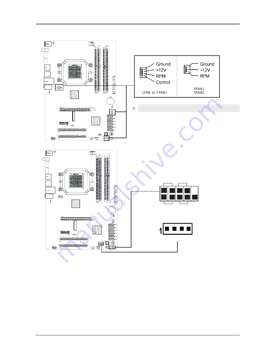
3.4 FAN Power Connectors
These connectors each provide power to the cooling fans installed in your system.
CFAN: CPU Fan Power Connector
SFAN1: System Fan Power Connector
3.5 Front Panel Switches & Indicators Headers
HD_LED (Red):
Hard Driver LED connector
This connector connects to the case-mounted HD LED cable, and the LED will light when the
hard drive(s) is/are being accessed.
RST (Blue):
Reset Switch
This connector connects to the case-mounted reset switch which allows you to reboot without
having to power-off the system and thus prolonging the life of the power supply or system.
PWR_ON (Black):
Power Switch
Depending on the setting in the BIOS setup, this switch serves two functions which will allow
you to power-on/off the system or to enter the suspend mode.
PWR_LED (Green):
Power/Standby LED
When the system's power is on, this LED will light. When the system is in the S1 (POS - Power
on Suspend) or S3 (STR - Suspend to RAM, optional) state, it will blink every second.
SPEAKER (Yellow or Black):
Speaker Connector
This 4-pin connector connects to the case-mounted speaker.
These fan connectors are not jumpers. DO NOT place
jumper caps on these connectors.
+
-
+
-
PWR LED
_
PWR ON
_
HD LED
_
RST
Speaker


