


6
IT
- Segnali e dispositivi di sicurezza
Durante il normale funzionamento, i segnali LED hanno i seguenti significati:
a. Quando l‘acceleratore è in posizione neutra, non è accesa né la LED rossa né la LED verde.
b. Il LED rosso si accende quando il veicolo è in movimento in avanti o indietro. Durante la
frenata, il LED rosso lampeggia velocemente.
c. I LED verde si accende quando il generatore di gas e in max. posizione avanti o indietro.
Tramite segnali d’avviso, il regolatore richiama l‘attenzione su determinate condizioni:
1. Durante l´avvio, il processore controlla la tensione d’ingresso, quando è al di fuori dei limiti
consentiti, un tono duale con una pausa di un secondo tra i singoli segnali „bipbip, bip-bip,
bip-bip-“ lo segnala.
2. Quando il segnale d’ingresso non è corretto, sarà generato un suono con una pausa di due
secondi tra i singoli segnali „bip-,-bip, bip-“
Questo regolatore è dotato di una serie di dispositivi di sicurezza per un funzionamento sicuro:
1. Spegnimento sottotensione:
Non appena la tensione di una batteria LiPo, per un periodo di 2 secondi, va sotto la soglia
impostata, il motore si spegne. Notate che il motore non può essere riavviato, se la tensione di
una cella è inferiore a 3,5 V. Batterie NiCd o NiMH con una tensione compresa tra 9,0 V e
12,0 V, sono trattate come una batteria LiPo a tre celle. Le batterie con meno di 9.0 V come un
due-celle LiPo-Pack. Se per esempio, una batteria NiMH ha una tensione di 8,0 V, e la soglia
è impostata a 2,6 V per cella LiPo, l‘arresto avviene a 5,2 V (2 x 2,6 V). Cosi anche le celle di
NiCd, sono efficacemente protetti contro una scarica profonda.
2. Spegnimento per sovratemperatura:
Appena la temperatura del regolatore, per una durata di 5 secondi, supera il valore di 95 ° C, il
motore si spegne. Dopo lo spegnimento, è necessario lasciare raffreddare il regolatore,
altrimenti il regolatore sarà danneggiato. Questa funzione non può essere disabilitata!
3. Segnale d´ingresso difettoso
Se il segnale d’ingresso per un periodo di 0,2 sec è rilevato come errato e motore si spegne.
GB
- LED’s, errors and protection
In normal use the LED will illuminate as follows:
a. If the throttle control is in the neutral position, neither the red or green LED will illuminate.
b. The red LED will illuminate if the vehicle is driving forwards or in reverse. If the vehicle is
braking, the red LED will flash rapidly.
c. The green LED will illuminate when the vehicle is at full throttle either forwards or in reverse.
In certain circumstances the ESC will omit an acoustic tone to warn you of a problem:
1. On switching on, the ESC will check the battery pack voltage and if it falls outside the correct
values it will omit double signals followed by a 1 second pause: “beep-beep-, beep-beep-,
beep-beep-”
2. If the ESC does not receive a signal from the transmitter it will omit single signal followed by a
2 second pause: “beep-, beep-, beep-”
The ESC has ben equipped with a series of protective circuits to ensure safe operation:
1.
Low voltage cut-off:
If the voltage drops below the set value for more than 2 seconds the ESC will switch the motor
off. Please note that the motor cannot be started again if the voltage is below the choosen
value per cell. If a NiCd or NiMH pack with a voltage of between 9 and 12 Volts is connected,
the ESC will treat is as if it was a 3 cell LiPo pack. If the pack voltage is below 9.0 Volts, the
ESC will react as if it was a 2 cell LiPo pack. For example, if a NiMH pack is connected with a
nominal voltage of 8 Volts and the cut-off value is set to 2.6 Volts per cell, the ESC will
switch the motor off at 5.2 Volts (2 X 2.6 V). This will protect the NiMH packs from ‘deep
discharge’.
2.
Temperature cut-off
If the internal temperature of the ESC rises above 95°C for more than 5 seconds the motor will
switch off. After the ESC switches off it has to cool down before operating again. Otherwise the
ESC will be damaged.
This function should not be disabled!
3. Signal loss
If the signal is lost for more than 0.2 seconds the ESC will switch the motor off.
IT
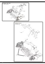
- Apprendimento della corsa gas / freno
Per prestazioni ottimali, il regolatore deve essere calibrato. In tal modo, le tre
posizioni avanti, indietro e la posizione di folle devono essere specificata.
Ci sono tre ragioni per la necessità di calibrazione:
• Durante il primo avvio
• Effettuando un cambio della trasmittente
• Dopo una riprogrammazione del punto neutro e / o la corsa del servo del
trasmettitore
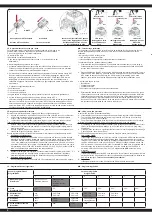
Durante la regolazione procedere come segue:
1. Accendete il radiocomando, durante che la ricevente è spento. (Attenzione con sistema di
Futaba: In certi casi la funzione del gas è invertita). La corsa servo deve essere in posizione
neutrale. Fare attenzione che la funziona ABS sia spenta.
2. Poi accendere la ricevente tramite l‘interruttore sul regolatore. Tenendo premuto il tasto ‚SET‘.
Questo vi porterà alla modalità di calibrazione, il LED inizia a lampeggiare. Appena il LED
lampeggia, rilasciare il pulsante. Se non si rilascia il tasto ‚SET‘ subito dopo il LED inizia a
lampeggiare e si entra nella modalità di programmazione. Se non si desidera questo, è
necessario a spegnere nuovamente il regolatore. La figura seguente mostra il processo d’inizio
di calibratura.
3. E´possibile configurare tre parametri:
• Posizione neutra
• Fine corsa marcia avanti
• Fine corsa marcia indietro
In seguito trovate le immagini,dove sono presentati i processi e le procedure graficamente.
4. Portare la leva del gas in posizione neutrale e premere il tasto ‚SET‘, il
LED verde lampeggia una volta e il motore emette un suono. Portare la leva del gas in posizione
finale per il movimento in avanti e premere il tasto `SET il LED verde lampeggia due volte e il
motore emette due suoni. Portare la leva del gas in posizione finale per il movimento indietro
e premere il tasto `SET`, il LED verde lampeggia tre volte e il motore emette tre suoni. Attendere
tre secondi, dopodiché è terminato il processo di calibrazione.
GB
- Throttle range calibration
To ensure that your ESC operates correctly it has to be calibrated. During this process the full
throttle, stop and brake positions will be set. There are 3 occasions when the unit must be
calibrated.
• Before using the ESC for the first time
• If you change to a new transmitter
• If the neutral point or servo throw is changed within your transmitter
To calibrate the system, please proceed as follows:
1. Ensure that the receiver is switched OFF and switch ON the transmitter. If you are using a
Futaba transmitter. The throw should be set to neutral. If the transmitter is fitted with an ABS
function this must be de-activated.
2. Press and hold down the ‘SET‘ button on the ESC and switch the receiver switch ON. This will
switch the ESC into Calibration’ mode and the LED will begin to blink. If you fail to release the
‘SET’ button as soon as the LED blinks, the ESC will enter ‘Programming’ mode. If this
happens, you will have to switch the ESC off and start again to enter ‘Calibration’ mode.
3. Parameters can be set here:
• Neutral point
• Full throttle forwards
• Full throttle reverse
The procedure for setting these 3 points is outlined below:
4. Ensure that the throttle control is in the neutral position and press the ‘Set‘ button. The green
LED will flash once and the motor will omit a beep. Move the throttle control to the full throttle
(forwards) position and press the green ‘Set‘ button. The green LED will flash twice and the
motor will omit 2 bleeps. Move the throttle control to the full reverse position and press the
‘Set‘ button. The green LED will flash 3 times and the motor will omit 3 bleeps. 3 Seconds after
this procedure has been followed, the motor is ready for use.
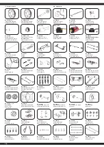
Gusto presa sul SET Stampato
interruttore
Lasciate che il pulsante SET quando
le luci rosse lampeggiano crostate
Hold the SET keep button
Turn on the switch
Release the SET button as soon
as the red LEDstarts to blink
ON/OFF
1
ON/OFF
Set
LED
Neutral point
first click
second click
third click
Point of full throttle
Point of full brake
2
LED verde
lampeggia una volta
Green LED flashes
once
LED verde
lampeggia due volte
Green LED
flashes twice
LED verde
lampeggia tre volte
Green LED
flashes thrice
Set
Set
Set
Le caselle grigie indicano l’impostazione consigliata.
The fields which are shaded in grey indicate the factory recommended settings.
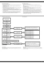
IT
- Programmazione del regolatore
GB
- Programming the ESC
Fase di programmazione
Program Mode
Valori del programma
Program Value
1
2
3
4
5
6
7
8
1. Modalità di guida
Drive Mode
In avanti freno on
Forwards, brake on
avanti / indietro,
freno on
forwards / reverse,
brake on
2. Freno
Drag Brake Force
0 %
5 %
10 %
15 %
20 %
25 %
30 %
40 %
3. Sottotensione
Low Voltage
aus
OFF
2,6 V/Zelle
2,6 V/cell
2,8 V/celle
2,8 V/cell
3,0 V/celle
3,0 V/cell
3,2 V/celle
3,2 V/cell
3,4 V/celle
3,4 V/cell
4. Start modo
Start Mode
sanft
soft
normal
normal
aggressivo
aggressive
molto aggressivo
very aggressive
5. Forza frenante massima
Brake Max.
25%
50%
75%
100%


