


5
Motor
#A
#B
#C
ESC
Channel 2
Switch
Receiver
Channel 1
Servo
Plus pole
red cable
Minus pole
black cable
Set
ON/OFF
IT
- L‘uso del regolatore
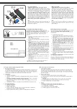
Collegamento della ricevente, la batteria e il motore
Collegare il regolatore, la ricevente, la batteria, il servo e il moto-
re in base alla seguente tabella. Prestare attenzione alla polarità
della batteria di alimentazione. Collegare il fi lo rosso al terminale
‚+‘ e il nero con il „-“ della batteria. I terminali # ‚A‘ # # B e C‘ de-
vono essere collegati ai morsetti del motore. Il tasto ‚SET‘ viene
usato per la programmazione. Collegare l‘uscita del „canale 2“
della ricevente con il regolatore. Osservate l‘assegnazione dei
canali sul telecomando. Collegare le uscite del regolatore ai mor-
setti del motore. Non esiste un´assegnazione consigliata. Dopo
che tutto è collegato, è necessario di eseguire un test. Se il mo-
tore gira nella direzione sbagliata e consigliato di invertire i cavi
oppure verifi care il tasto reverse sul radiocomando.
Nota
È possibile utilizzare la funzione inversa del radiocomando per
cambiare la direzione di rotazione del motore. È necessario di
riprogrammare il regolatore.
GB
- Using Your ESC
Connecting the Receiver, Battery Pack and Motor
Connect the ESC, the receiver, the battery pack, the steering
servo and the motor together following the diagram below.
Ensure that you observe the correct polarity of the battery pack.
The red cable should be connected to the ‘+‘ Plus Pole and the
black cable to the ‘-‘ Minus Pole. The ’#A’, ’#B’ and ’#C’ plugs
are connected to the motor. The ‘SET‘ button initiate the pro-
gramming mode. The ESC should be plugged into the throttle
channel of your receiver which is normally channel 2. If in doubt,
check your Radio- Control System’s instructions. The 3 Motor
wires can now be connected, these connectors can be plugged
in any order, and if the motor rotates in the wrong direction any 2
of the wires should be swapped.
Note:
You can use the servo reverse function of your transmitter to
reverse the motor direction but the ESC will have to be re-cali-
brated afterwards.
IT
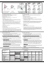
- Programmazione del gruppo integrato di FailSafe
1. Descrizione della Funzione
L’unità FailSafe è concepita principalmente per l‘utilizzo sulle imbarcazioni e sui veicoli. Serve
per evitare la perdita del modello, determinando la chiusura del gas, nell’eventuale assenza
di segnale. Se la ricevente perde il segnale della trasmittente, il servo del gas o regolatore di
velocità ritorna automaticamente sulla posizione programmata inizialmente.
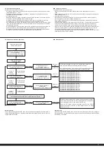
2. Impostazione
a. Accendere la trasmittente
b. Accendere la ricevente. Il segnale LED lampeggia continuamente e indica che la ricevente
è pronta.
c. Spostare sul trasmettitore la leva dell‘acceleratore nella posizione di freno, o zona spento
nel regolatore di velocità. Tenere la leva del gas su questa zona.
d. Premere il pulsante Imposta sul ricevitore. Il segnale LED lampeggia per 3 secondi (vedi
illustrazione a sinistra).
e. L‘impostazione è salvata e si può portare la leva dell’acceleratore in posizione neutra.
3. Prova delle impostazioni
a. Accendere la trasmittente.
b. Accendere la ricevente.
c. Spegnere la trasmittente.
d. Ora la ricevente perde il segnale e conduce il servo del canale gas o il regolatore di
velocità sulla posizione in precedenza programmata.
e. Seguire la procedura descritta sopra, il processo FailSafe funziona correttamente.
GB
- How to setup the fail safe function
1. The instruction of function
The function of protection of losing control is mainly for r/c boats and cars and keeps them
away from damage through throttle channel. When the receiver is out of control signal, the
receiver of throttle will automatically return to the initial position which set up before starting to
avoid the error action :
2. How to set the function
a. Switch on the transmitter power and enter into the working condition
b. Connect the receiver with power and enter into the working condition, the signal light on
receiver will blink
all the time.
c. Control the throttle of transmitter and keeps the servo or ESC in the neutral position.
d. Press the setting button, the LED will be flash for 3 seconds (see on pict. left).
e. Release the setting button. The setting is finished.
3. Testing
a. Switch on the transmitter and enter the working condition.
b. Contact the receiver with power and enter the working condition.
c. Turn off the power of transmitter.
d. The throttle of servo will be set automatically.
e. Finish these steps above means the setting is ok.
2,4 GHz
Antenne
Antenna
Empfänger/Receiver
Connettore di
collegamento
Binding Plug
Fail Safe
Setup LED
IT
- Allacciare la trasmittente alla ricevente
In un moderno sistema di 2,4 GHz, è indispensabile che la
trasmittente e la ricevente vengano connesse insieme a bordo del
modello. La ricevente accetta quindi solo i segnali della
trasmittente. Se per qualsiasi motivo si dovesse effettuare un
nuovo allacciamento“connessione”, eseguire le seguenti
operazioni:
1. Sostituire nella trasmettente le batterie scariche con altre ca-
riche o nuove.
Lasciare spenta la trasmettente.
2. Inserire la spina di accoppiamento in dotazione nell’uscita del
canale 3.
3. Collegando la batteria con la ricevente, si accende il sistema
ricevente.
Secondo la versione di software usata, la ricevente seg-
nala in modo differente la modalità di binding. (esempio:
il Led può lampeggiare, restare accesa o completamente
spenta).
Il processo di binding in se è uguale per tutte le ver-
sioni. Il Led sulla ricevente inizia lampeggiare e cosisegnala
che la ricevente si trova in modalità di binding.
4. Tenere premuto il pulsante di connessione sulla trasmittente,
mentre si accende la stessa. E. Il trasmittente inizia a lam-
peggiare e cosi segnala che si trova in modalità di binding.
5. Rilasciare il pulsante di connessione della trasmettente e ri-
muovere la spina di connessione nella ricevente. Spegnere
laricevente e la trasmittente.
6. Adesso spegnete la trasmittente. Il sistema memorizza il col-
legamento.
7. Installare correttamente tutti gli accessori e controllare con
molta attenzione.
8. Se la funzione non avesse successo, ripetere la procedura
di connessione.
L’illustrazione seguente mostra grafi camente il processo di
connessione e specifi ca gli element da utilizzare.
GB
- Binding the receiver to the transmitter
The receiver must be bound to the transmitter to ensure that the
receiver will only react to signals from that transmitter.
If you wish to re-bind the receiver with the transmitter please pro-
ceed as follows:
1. Put the battery into the model.
Now connect the battery to the speed control in the model.
2. Plug the binding plug (included) into the channel 3 socket on
the receiver.
3. Switch the receiver system on.
Depending on your soft-
ware version of your receiver indicates the different bin
-
ding mode (instead of flashing lights for example LED or
remains out completely).
The binding process as such is in
all versions. The receiver LED will begin to flash indicating
that the receiver is in bonding mode.
4. Press and hold down the binding button on the transmitter
whilst switching it on.
5. The transmitter will begin to flash indicating that the receiver
is in bonding mode.
5. Release the binding button on the transmitter and turn off the
controller. Release the binding plug from the receiver.
7. Switch of the transmitter. And remove the binding wire. The
system be bound at the next start .
8. If the receiver fails to bond or does not function after bond-
ing repeat the above procedure until a successful bonding is
achieved.
We encourage you now to activate your receiver‘s built-in Failsafe
unit.
On delivery it is turned off.
Mount the 2.4 GHz antenna vertically as shown in the diagram. Do
not allow any metal object to come into contact with the antenna or
to shield it as this will reduce the range.


