background image

8

ESC

On/Off

Battery

ESC/Battery
Connector

GB - Getting Started

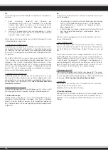
Make sure that all parts from the box content are included. Trans-
mitter, Car, Charger, Balancer, battery pack.

The  battery  pack  has  to  be 
charged before use. Plug the 
charger  into  a  230V  outlet. 
Connect  the  charger  to  the 
balancer and the balancer to 
the balancer plug of the bat-
tery  The  average  charging 
time of the empty battery is 
about 5 - 7 hours.

Place 8 pieces of AA batteries into the 
transmitter.  If  rechargebale,  please 
also make sure these are fully charged.

Read  the  chapter  for  usage  of  the 
transmitter and its controls carefully. 

Turn the radio off and make sure all the 
trim  buttons  on  the  transmitter  are  in 
neutral position.
You have purchased a RTR model, which 
means  it  should  be  ready  for  immedia-
te  use  after  charging  all  batteries.  You 
need  to  check  the  car,  electronics  and 
all  plastic  parts  after  each  use  to  make 
sure no parts are damaged. 

Also all the 

moving parts must be checked for their clearance, bolts and 
screws that they are tight.

Now  put  the  battery  into  the 
battery  holder  in  the  vehicle. 
Make  sure  that  the  battery 
holder is secured properly with 
the  2  included  clips  for  the 
battery  holder.  Now  connect 
the battery to the speed con-
trol in the model.
Keep the car in the air in case 
that the motor turns at full po-
wer.
Switch the speed control on the On / Off switch. Set the model on 
the ground and test it for proper functioning. Steering right/ left, 
throttle/ brake, forward and backward. If the wheels do not point 
straight forward even though the steering wheel on the transmitter 
is in neutral, you can adjust it with the trim button on the trans-
mitter.
Trim L/R = steering
Trim V/R = forward/backward

Should  the  wheels  rotate  forward  or  backward,  even  though  no 
command was given through the transmitter, then also the throttle 
needs to be trimmed on the transmitter.
We encourage you now to activate your receiver‘s built-in Failsafe 
unit. 

On delivery it is turned off. 

Leave the throttle lever in neutral position (see chapter Fail Safe). Press 
the fail-safe button on the receiver until it flashes and let go to activate. 

Check this principle in an electric vehicle only in the neutral 
position of the throttle, because otherwise the model goes 
into the previously programmed throttle position in a loss of 
the transmitter signal.

Now you can make the first test drive. If this is your first rc car, we 
recommend to drive it on a small test track to familiarise yourself 
with the control of the vehicle and the controls of the transmitter. 

Attention! 

Your  vehicle  has  a  pivot  front  suspension.  This  has  a  number  of 
advantages. It is very robust and easy to maintain. The set-up of the 
car has been done so the drive shaft will not pop out. As with any 
model, screws and bolts can losen during break-in of the car. This 
can result in tolerance of the drive shaft. The drive shaft can then 
pop out if high pressure is applied. 
The inner ball screw (item No.: 505081) will enable you to adjust 
the tolerance resulting in fine adjustments of the track width. For 
best results when setting up the pivot ball for the first time, please 
always adjust the upper and lower pivot in the same way. Fasten 
as far as the pivot can still be pulled up and down easyly but not 
as far that it will pop out if you give full steering angle. The outer 
plastic socket screw (item No.: 505080) is only used for securing of 
the steering knuckle. This should not be too tight, otherwise the 
steering is not smooth and the handling can be adversely affected.

Important!

By using LiPo batteries take care that  the undervoltage shutdown 
is activated, see page 20 - 23
Otherwise, your LiPo battery can be damaged by deep discharge. 
We recommend a cut-off voltage of 3 V per cell

On/Off

L/R  F/B

Trim

50 5080

50 5081

07 9996

50 5079

Balancer

Charger

Battery

Summary of Contents for 05 3260

Page 1: ...Abschluss der Montagearbeiten Safety precautions This radio control model is not a toy Suitable for persons over 14 years First time builders should seek advice people having building experience in o...

Page 2: ...llten Pl tzen und in der N he von kleinen Kindern Fahren Sie nie auf ffent lichen Stra en Betreiben Sie dieses Modell niemals auf nassen Fl chen die elektronischen Bestandteile k nnten besch digt wer...

Page 3: ...your model over people and never operate the model in way which may endanger people small children or animals Never operate the model on rain or over damp surfaces this may damage the electronics If...

Page 4: ...el dann wenn das Modell nicht mehr l uft Bitte sorgen Sie f r fachgerechte den gesetzliche Vor schriften entsprechende Entsorgung der Elektrobauteile Fernsteuerung Ladeger t und Modell usw Bitte wer f...

Page 5: ...s or commune Normally discharge the accus when the model stops running All parts of this model should be disposed of correctly in particular electronic components may be subject to local restrictions...

Page 6: ...mpfer l Louise Shock Oil Louise 28 1904 Karosseriesplint Bodychips 05 9273 Montagest nder mit Drehteller Car Stand rotatable 19 3130 Sto d mpfer St nder Shockstand 05 0590 Inbussteckschl sselset Hexag...

Page 7: ...lstellung zu trimmen Wir empfehlen Ihnen nun die in Ihren Empf nger in tegrierte Failsafe Einheit zu aktivieren Im Auslieferzustand ist diese deaktiviert In dem Sie w hrend Sie den Gashebel am Sender...

Page 8: ...mitter then also the throttle needs to be trimmed on the transmitter We encourage you now to activate your receiver s built in Failsafe unit On delivery it is turned off Leavethethrottleleverinneutral...

Page 9: ...tz lich st runempfindlicher Andererseits ist aber das Binden eines Empf ngers an den zugeh rigen Sender unbedingt notwendig Der 2 Kanal Sender ist f r die Lenkung und die Fahrfunktion mit hochwertigen...

Page 10: ...ssen Sie sich von Ihrem Fachh ndler beraten Nachdem die Zellen voll aufgeladen sind trennen Sie die Verbindung zum Sender bzw zur Ladebuchse der Empfangsanlage und entfernen das Ladeger t aus der Stec...

Page 11: ...ber die Ladebuchse la den bitte Batteriefachdeckel ffnen Dies dient der K hlung G F 2 4 GHz Antenne Empf nger 2 4 GHz Antenna Receiver GB Controls Side View 1 Programming Box 2 2 4 GHz Antenna 3 Steer...

Page 12: ...ndeprozedur Die folgende Abbildung stellt grafisch den Bindevorgang dar und kennzeichnet die einzelnen Elemente die bedient werden m ssen GB Binding the receiber to the transmitter As with all modern...

Page 13: ...an dass der Empf nger betriebsbereit ist c Bringen Sie den Gashebel am Sender in die Neutralposition Ihres Servos oder Speedreglers d Dr cken Sie die Setup Taste am Empf nger Die Signal LED blinkt f...

Page 14: ...d to the end of it s range Mit dieser Funktion werden die Vor und R ckw rtssteuerung sowie die Geschwin digkeit gesteuert Wenn der Steuergeber nach hinten gezogen wird bewegt sich das Fahrzeug nach vo...

Page 15: ...l f r Lithium als auch f r Nickelakkus ist eine Unterspannungs abschaltung integriert Ein bertemperaturschutz und eine digitale berpr fung des Eingangssignals sorgen f r einen st rungsfreien Betrieb S...

Page 16: ...am Sender eine evtl vorhandene ABS Funktion ausgeschaltet haben GB Using Your ESC Connecting the Receiver Battery Pack and Motor Connect the ESC the receiver the battery pack the steering servo and th...

Page 17: ...Fahrzeug sich vor oder r ckw rts bewegt Beim Bremsen blinkt die rote LED schnell c Die gr ne LED leuchtet sobald der Gasgeber sich in der max Vor oder R ckw rtsposition befindet GB 2 Press and hold d...

Page 18: ...rzogen wird kann es trotzdem einmal zu einem Problem kommen In der folgenden Tabelle sind evtl Probleme deren Grund und zugeh rige L sungsm glichkeiten aufgelistet GB In certain circumstances the ESC...

Page 19: ...as well as the ESC connecting cable Der Motor hat die falsche Drehrichtung The motor turns in the wrong direction Die Verbindungen zum Motor wurden ver tauscht The motor connecting cables are swapped...

Page 20: ...sen Release button Taste l sen Release button Taste l sen Release button Taste l sen Release button Taste 3 Sek halten Press the button for 3 seconds Taste 3 Sek halten Press the button for 3 seconds...

Page 21: ...siseinstellungen Default Setting 1 Fahrmodus Drive Mode vorw rts Bremse an Forwards brake on vor r ckw rts Bremse an forwards reverse brake on 2 Zugbremse Drag Brake Force 0 5 10 15 20 25 30 40 3 Unte...

Page 22: ...z B dem Getriebe verbunden 6 Max r ckw rts In diesem Men kann die max Geschwindig keit f r r ckw rts fahren eingestellt werden 7 Bremskraft min In diesem Programmierschritt kann einge stellt werden w...

Page 23: ...l Zone which is the area between forwards and reverse or braking can be set to Narrow Normal or Wide as shown in the illustration below This Zone can be set for both stick or pistol grip type transmit...

Page 24: ...gem er Verwendung des Akkus besteht Brand oder Ver tzungsgefahr berladen zu hohe Str me oder Tiefentladen zerst rt die Zelle Vor mechanischer Belastung Quetschen Dr cken Biegen Bohren sch tzen Akkus k...

Page 25: ...Overcharging too high power or discharging at low level destroys the cell Protect from mechanical stress squeezing pushing bending drilling Never open or cut open do not throw into fire keep away from...

Page 26: ...g zu niedrig Akku laden bertemperaturabschaltung Speedregler abk hlen lassen Antriebswellen vorn fallen heraus zu gro e Spurbreite Spurbreite verringern GB Troubleshooting Problem Possible cause Solut...

Page 27: ...5072 50 5085 50 5076 07 9989 Montage Heckgetriebe Rear gear assembly diagram 50 5078 50 5075 50 5074 50 5073 50 5024 50 5145 50 5023 50 5024 50 5076 50 5071 50 5085 07 9989 No 50 5155 Differential vo...

Page 28: ...icht unter Spannung stehen aber auch nicht herausfallen k nnen Die u ere Kunststoff Inbusschraube 505080 dient nur zum sichern des Achsschenkels auf der Kugelkopfschraube Diese sollte auf keinen Fall...

Page 29: ...29 50 5054 50 5097 50 5087 50 5054 07 9989 50 5082 07 9996 50 5028 Montage Heckgetriebe Rear shaft assembly Montage Sto d mpfer Shock assembly 50 5064...

Page 30: ...30 50 5029 50 5029 Montage Servo Saver Buffer assembly Montage Lenkservo und Radioplatte Buffer assembly 50 5027 03 3215 07 9841 50 5093...

Page 31: ...31 50 5126 22 Z T 50 5026 13 0046 Montage Motor Motor assembly...

Page 32: ...lter Suspension fixed mount set No 50 5090 Radachse vorn hinten Wheel axle No 50 5027 Radioplatte Radio tray set No 50 5096 Spurstange Steering rod connecting set No 50 5100 Querlenker vorn unten Fron...

Page 33: ...50 5082 Achsschenkel hinten Rear shaft hub No 50 5029 Servo Saver Set Steering saver No 50 5074 Differentialgeh use Differential case set No 50 5028 Querlenkerstift Suspension arm shaft No 50 5079 Ach...

Page 34: ...head machine cross screw No 50 5061 M2 11 Pin Pin No 08 1452 60A Speedregler Brushless Speedcontroller Brushless No 50 5048 M3 10 Blechschraube Round head selftapping cross screw No 50 5053 M3 6 Senk...

Page 35: ...ern Nylon Nut No 50 5045 2 5 mm E Clip E clip No 05 0450 Antennenr hrchen Aerial tube No 07 9989 10 15 4 Kugellager Ball bearing No 05 9274 10 15 4 Karosseriesplint Body clip DE Ersatzteile GB Spare p...

Page 36: ...No 505116 1 10 Reifen Felgen Stra e Wheels Rims Street No 505148 Getriebeabdeckung Lexan Gear covering Lexan No 081453 30 60A Programmierkarte Programming card No 074416 High End 9712 MG Servo Servo N...

Page 37: ...onstante Stromst rke der Akkus er h ht sich auch die Fahrleistung Deshalb ist es auch wichtig bei Lipo s die Unterspannungsabschaltung Ihres Speedreglers zu aktivieren siehe Anleitung da der Akku sons...

Page 38: ...38...

Page 39: ...39...

Page 40: ..._______________ E mail _______________________________ Bitte senden Sie den Katalog f r mich an folgenden Fachh ndler Please send the catalogue to the following specialist dealer Ihr Fachh ndler Your...

Reviews: