


Page 6 of 11
Assembly Instructions: Multi Section Cupboard
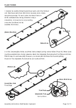
7. Align the Valance White Cams with the Box
Base Cam Bolts, then lock each cam securely in
place. See Page 4 for help with cams.
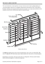
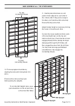
8. The following instructions will cover the assembly
process for a single box. Simply repeat this process for
each box in your design, referring to the engraved box
numbers on each of the Box Sides, Box Top, Box Base
and Box Back, as well as the Parts Diagram to confirm the
configuration of Shelves and/or Dividers for each box.
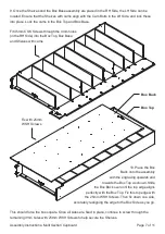
With the front edges toward the floor, fit the Box Top to the RH Side and secure with 45mm
CSK Screws. Then proceed to add all the Shelves. Wherever (if) the Box Sides feature
central Cam Bolts, place one of the Shelves with cams, with the cam facing
towards the Box Base.
If the box has
more than one Divider
, start by placing all the necessary shelves between the
Dividers. Wherever (if) the Divider features a central Cam Bolt, place one of the Shelves
with cams. After locating the other normal Shelves, lock these Shelf cams
into place to hold the structure together.
Note about Dividers
Note that the following example has no Dividers.
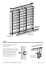
BOX ASSEMBLY
Box Base
RH Side
Cams to the floor
Valance
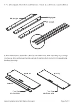
If the box has
just one Divider
, the Box Top and Box Base can now be
attached either end of the Divider, before fixing with 45mm CSK Screws.
Pilot drill, then fix with
45mm CSK Screws
Short tenons for Outer Box Sides
Long tenon
Box Top
Dowel holes to
the floor, engraved
label facing towards


