background image

Page 1 of 11

Assembly Instructions: Multi Section Cupboard

5mm Pozi 

Screwdriver

Power Drill +

2mm Drill Bit

& Pozi Drives

Cupboard – Multi

Assembly Instructions

FIXINGS INCLUDED

YOU WILL NEED

EXTRA

•  Take great care handling and lifting parcels
•  Open parcels with care to avoid damage
•  Check the label to see the contents of each parcel
•  If you have ordered several items, keep it simple: only unpack one item at a time
•  Use the the Parts Diagram sheet to identify and distinguish between parts
•  Any questions: call us on 

01227 833333

, or email 

[email protected]

• 

You must fix your product safely in place. Depending 

on your situation, you may choose to use a drill, 
suitable screws and wall plugs

• 

You may wish to use Wood Glue to fix skirting in place

• 

To ensure a perfect fit with your room skirting board, 

you may use a saw to scribe the relevant parts during 
assembly

White Cam

Nickel Cam

Cam Bolt

25mm WSH 

Screw

Adjustable 

Foot

45mm CSK 

Screw

30mm CSK 

Screw

16mm PAN 

Screw

Connecting 

Screw

Dowel

Connector

in some cases

20mm PAN 

Screw

Magnetic 

Catch

Foot Plate

16mm CSK 

Screw

Magnetic 

Catch Plate

25mm CSK

Screw

Hinge

Plus Door Handles with Bolts as required

Summary of Contents for Cupboard - Multi

Page 1: ...tween parts Any questions call us on 01227 833333 or email sales jali co uk You must fix your product safely in place Depending on your situation you may choose to use a drill suitable screws and wall plugs You may wish to use Wood Glue to fix skirting in place To ensure a perfect fit with your room skirting board you may use a saw to scribe the relevant parts during assembly White Cam Nickel Cam ...

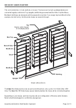
Page 2: ...on t worry it will become clearer as we work through Shown without Doors The Outer Box Sides are the ones at each end of the whole unit e g Box 1 LH Side Box 3 RH Side The Inner Box RH Sides have a spacer attached where the boxes will be connected together Depending on your design each box may have its own configuration of Shelves and or Dividers Refer to the Parts Diagram to confirm this arrangem...

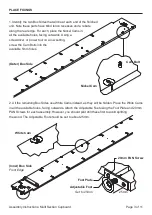
Page 3: ...first to avoid splitting the wood The Adjustable Foot should be set to about 25mm Outer Box Side Inner Box Side Front Edge Nickel Cam White Cam 20mm PAN Screw Foot Plate Adjustable Foot Set to 25mm 25mm Cam Bolt 1 Identify the two Box Sides that will be at each end of the finished unit Note these parts have blind tenon recesses and a rebate along the rear edge For each place the Nickel Cams in all...

Page 4: ...urn the Divider over and screw in Cam Bolts in the same holes on the opposite side 4 On taller units one or more of the outer Shelves in the outer boxes may have a cam hole Place Nickel Cams in these 1 Screw in the Cam Bolt up to the shoulder into the 5mm hole in one part 2 Push the Cam facing outwards into the corresponding hole on the other part 3 Push the two parts together so that the Cam Bolt...

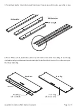
Page 5: ... Place White Cams in the Box Base Box Top and Valance cam holes Depending on your design the Valance strip could be taller than this example Screw Cam Bolts into the 5mm holes along the Box Base front edge 5 For all the Uprights fit Cam Bolts to all 5mm holes There is also a 6mm hole leave this for now RH Upright Mid Upright s LH Upright ...

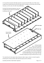
Page 6: ...Shelves Wherever if the Box Sides feature central Cam Bolts place one of the Shelves with cams with the cam facing towards the Box Base If the box has more than one Divider start by placing all the necessary shelves between the Dividers Wherever if the Divider features a central Cam Bolt place one of the Shelves with cams After locating the other normal Shelves lock these Shelf cams into place to ...

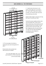
Page 7: ...d in place continue to screw through the remaining 3mm holes with 25mm WSH Screws to help secure the Shelves 10 Place the Box Back onto the assembly with the engraving upwards and towards the Box Top as shown Slide the Box Back over until the top edge aligns perfectly with the Box Top Fix this top edge with the 25mm WSH Screws Then fix down one side accurately realigning the edge to the Box Side a...

Page 8: ... bottom of each box Check that the screws engage properly before placing the larger female part through the RH Side and then engage the screw from the LH Side You may need two large pozi flathead screwdrivers to fully engage the Connecting Screws Fix with Connecting Screws Fix with Connecting Screws LH Upright Mid Upright RH Upright NOW ASSEMBLE ALL THE OTHER BOXES 12 Fit the Uprights to the Sides...

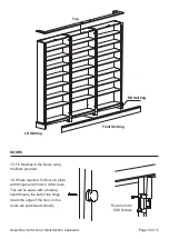
Page 9: ...CSK Screws 14 Depending on your design you may have one of a variety of different Top styles The most common is simply a solid Top board Alternatively you may simply have a Top lip This can be located using Dowels and glued or screwed from above This may be supplied as one single component or several parts which join together with a Connector using the hex key provided once in place Full Top Top L...

Page 10: ...kirting 15 Fix Handles to the Doors using the Bolts provided 16 Where required fix Doors in place with Hinges and 25mm CSK Screws This will be easier with a helping hand Ensure the butt of the hinge clears the edge of the door so the doors are positioned correctly Fix with 25mm CSK Screws DOORS ...

Page 11: ...to the required Box Tops with 16mm PAN Screws The Catch should be towards the front with the magnet facing outwards Then fix Magnetic Catch Plates to the back of any Doors with 16mm CSK Screws jali cupboard makeityours AND YOU RE DONE Fix with 16mm CSK Screws Fix with 16mm PAN Screws ...

Reviews: