4
mount bolts. Ensure that the oil cooler mount-
ing bracket is behind the lock washers. (Photo
1.)
24. Snap the oil cooler assembly downward until
the top of the mounting bracket is resting on
the upper motor mount bolt.
25. Tighten the upper and lower motor mount
bolts to their final torque value, 21-27 ft.lbs
(28-36 Nm).
Part 4: Fan wiring
FITMENT/INSTALL NOTE:
• Late-model H-D motorcycles with
CANBUS electrical systems access
power by using the included Deutsche
connector in their 6-pin diagnostic port
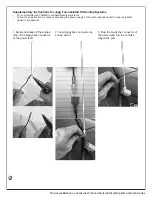
(SEE FINAL PAGE: “Supplementary
Instructions”)
• All other H-D motorcycles access pow-
er by connecting to the rear-brakelight
switch, explained below.
26. Install the included convoluted wire cover over
the fan wiring harness by inserting wiring into
the split. If the wire cover is too long, then it
may be trimmed with scissors.
27. Install the fan wiring harness by connecting
the female disconnect onto either prong of the
automatic fan switch.
28. Route the fan wiring harness under the right
side (air cleaner side) of the motorcycle along
the frame.
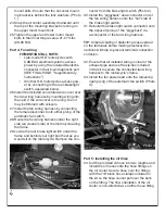
29. Locate the rear brake light switch under the
frame and behind your right boot heel as you
would sit on the motorcycle. Remove the con-
nector from the brake light switch (Photo 2).
30. Install the “piggyback” dual-connector end of
the fan wiring harness onto the “hot” side of
the brake light switch.
31. Reinstall the brake light switch connector onto
the exposed prong of the “piggyback” du-
al-connector of the fan wiring harness.
TIP: A liberal coating of dielectric grease spread
on the terminals before making electrical con-
nections will help to prevent terminal connection
corrosion.
32. Ensure that all installed wiring is clear of the
exhaust pipe and use the zip-ties included
in the kit to secure the connected fan wiring
harness to the motorcycle’s frame.
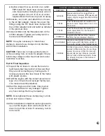
33. Install the fan power lead onto the remaining
open prong of the automatic fan switch (Photo
3).
Part 5: Installing the oil lines
34. Cut the provided oil hose into two lengths and
install the oil hoses onto the hose fittings on
the oil cooler. Secure hose over the fittings
with the 7/8” black hose clamps included in
the kit so the hose cannot pull over the barb
on the fitting. The flow orientation of the oil
cooler is non-directional, so either hose fitting
Photo 2.
Photo 3.


