background image

ADJUSTMENTS    9

41

9

   ADJUSTMENTS

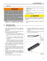
9.1   GENERAL ________________________________________________________________

1.

Adjustments and maintenance should always be
performed by a qualified technician. If proper

adjustment cannot be made, contact an authorized
Jacobsen Dealer.

2.

Replace, do not adjust, worn or damaged
components.

3.

Long hair, jewelry, or loose fitting clothing may get
tangled in moving parts.

4.

Do not change governor settings or overspeed the
engine.

9.2

BEDKNIFE-TO-REEL _______________________________________________________  

(Pre-adjustment Check)

1.

Check the reel bearings for end play or radial play.
There should be no end play or radial play. See
Section 9.16.

2.

Inspect the reel blades and bedknife to insure good
sharp edges without bends or nicks.

a.

The leading edge of the reel blades (B) must be

sharp, free of burrs and show no signs of rounding
off.

b.

The bedknife and bedknife backing must be

securely tightened. The bedknife must be straight
and sharp.

c.

A flat surface of at least 1/16 in. (0.15 cm) minimum

must be maintained on the front face of the bed-
knife. Use a standard flat file to dress the bedknife.

3.

If wear or damage is beyond the point where the
reel or bedknife can be corrected by the lapping
process, they must be reground.

4.

Proper reel-to-bedknife adjustment is critical. A gap
of 0.001 to 0.003 in. (0.0025 to 0.0076 cm) must be
maintained across the entire length of the reel and
bedknife.

5.

The reel must be parallel to the bedknife. An
improperly adjusted reel will lose its sharp edges
prematurely and may result in serious damage to
the reel and bedknife.

6.

Grass conditions will also affect the adjustment.

a.

Dry, sparse conditions will require a wider gap to

prevent heat buildup and damage to the reel and
bedknife.

b.

High quality grass with a good moisture content

requires a closer gap (near zero).

Figure 9A

Figure 9B


WARNING

To prevent injury, lower implements to the ground,
disengage all drives, engage parking brake, stop
engine and remove key from ignition switch before
making any adjustments or performing maintenance.

Make sure the mower is parked on a solid and level
surface. Never work on a mower that is supported
only by the jack. Always use jack stands.

If only the front or rear of the mower is raised, place
chocks in front of and behind the wheels that are not
raised.

!


CAUTION

Be careful to prevent entrapment of the hands and
fingers between moving and fixed components of the
machine.

!

1/16 in.
(0.15 mm)

B

Summary of Contents for Greens King IV Plus

Page 1: ...ctly used this machine can cause severe injury Those who use and maintain this machine should be trained in its proper use warned of its dangers and should read the entire manual before attempting to...

Page 2: ...ional information is needed contact your Jacobsen Dealer The serial plate is attached to the frame near the battery Jacobsen recommends you record these numbers below for easy reference 11524WILMARB L...

Page 3: ...Hoses 36 8 11 Hydraulic Oil 36 8 12 Hydraulic Oil Filters 37 8 13 Electrical System 37 8 14 Muffler And Exhaust 37 8 15 Tires 37 8 16 Wheel Mounting Procedure 38 8 17 Roll Over Protective Structure R...

Page 4: ...ht or in good artificial light Use caution when you operate the mower during bad weather Never operate the mower with lightning in the area f Inspect the area to select the accessories and attachments...

Page 5: ...was not made for ROPS a The ROPS is a safety device Keep the ROPS in the vertical and locked position Always use the seat belt when you operate the mower Make sure the seat belt can be released quick...

Page 6: ...ck or service the cutting unit blades Replace any damaged blades do not try to correct a damaged blade k Keep your hands and feet away from parts that move Do not adjust the mower with the engine in o...

Page 7: ...prolong the life of your machine and maintain its maximum efficiency Adjustments and maintenance should always be performed by a qualified technician If additional information or service is needed co...

Page 8: ...iesel Rating Min Cetane rating 45 Capacity 5 U S Gal 18 9 liters Governor Ball Type Governor Low Idle 1100 RPM High Idle 3400 RPM Lubrication Capacity 3 4 quarts 3 2 liter with filter Type SAE 20W SAE...

Page 9: ...spray 554598 Arm Rest 4139431 Grass Catcher 67891 Brush 62 in 68623 Fine Bristle Brush 68536 Green Sentry II Oil System Monitor 68669 Light Kit 2811910 Motor Light Brush Mounting Kit 2811909 Rear Roll...

Page 10: ...or V l Motor Aflv l Motor Kubota D722 E3B Diesel Kubota D722 E3B Diesel Net Installed Power ist instalovan v kon Installeret nettoeffekt Netto ge nstalleerd vermogen Installeeritud netov imsus Asennet...

Page 11: ...do operador Nivelul zgomotului la urechea operatorului Hladina hluku p sobiaca na sluch oper tora Raven hrupa pri u esu upravljavca Nivel sonoro en el o do del operador Ljudniv vid f rarens ra H va as...

Page 12: ...ura da pessoa com poderes para emitir a declara o em nome do fabricante que possui a documenta o t cnica que est autorizada a compilar o processo t cnico e que est estabelecida na Comunidade Semn tura...

Page 13: ...49 1 2001 BS EN ISO 5349 2 2001 The mower was tested for Whole Body vibration levels The operator was in the normal position to drive the vehicle with two hands on the steering mechanism The cutting d...

Page 14: ...battery 1 Connect positive terminal to positive terminal 2 Connect negative terminal on good battery to frame of vehicle that has dead battery Read operator s manual Do not allow untrained operators...

Page 15: ...while loosening nut Located on lift arms WARNING Read manual for service To prevent cuts do not turn reel by hand Use socket wrench or Turf Groomer knob to turn reel Located on reel frame 4181860 WAR...

Page 16: ...e 4 6 a b i o d e g r a d a b l e h y d r a u l i c f l u i d O r d e r 5 0 0 3 1 0 5 f o r 5 g a l p a i l U s e o f AT F D e x t r o n I I o r I I I i s a n a p p r o v e d a l t e r n a t e f l u i...

Page 17: ...IMMEDIATELY A B C D 2812066 8 12 p s i 55 83 kPa 105dB LWA 4141266 3 5 30 30 09 74 4 Brake Reel Switches Wiring Tire Pressure Noise Level Engine Oil Pressure Backlap Switch Ignition Switch Start RUN...

Page 18: ...Right Reel Center Reel Left Reel Reel Forward Rotation Reel Off Reel Reverse Rotation Parking Brake Disengaged Transport Mow Neutral Reverse Traction Lever Parking Brake Engaged Charging System Fuse I...

Page 19: ...t they represent Learn the location and purpose of all of the controls and gauges before operating this mower Read Manual Off Run Start Engine Fast Slow Engine Throttle Forward Reverse Reel Rotation F...

Page 20: ...Volt Meter F Ignition Switch G Mechanics Backlap Switch H Light Switch Optional J Lights Fuse Optional K Charging Circuit Fuse L Interlock System Fuse M Parking Brake Light N Oil Pressure Light P Thr...

Page 21: ...restarting engine P Throttle Regulates Engine Speed Push Lever forward to increase or pull lever back to decrease engine speed R Fuse Glow Plug 40 Amp fuse protecting glow plug circuit S Glow Plug Swi...

Page 22: ...to run during tests 5 or 6 3 Refer to the chart below for each test and follow the check 4 marks across the chart Shut engine off between each test Test 1 Represents normal starting procedure The ope...

Page 23: ...bstruction or if the machine begins to vibrate abnormally Have the equipment repaired before resuming operation 10 Slow down and use extra care on hillsides Read Section 6 7 Use caution when operating...

Page 24: ...15 seconds 6 Allow the engine to become warm and properly lubricated before operating at high RPM Figure 6A 6 5 STOPPING PARKING _____________________________________________________ To stop Remove y...

Page 25: ...traction and steering control 1 If the mower tends to slide or the tires begin to mark the turf angle mower into a less steep grade until traction is regained or tire marking stops 2 If mower continu...

Page 26: ...Inches with 1 Yard Level A Millimeters with 1 Meter Level A Slope in Degrees Slope Grade 3 4 8 8 3 100 5 7 10 0 150 8 5 15 6 9 5 16 7 200 11 3 20 0 7 5 11 8 20 8 225 12 7 22 5 9 250 14 25 0 275 15 4...

Page 27: ...ch successive pass should overlap the previous one by a few inches 6 After all of the straight passes have been made make one final pass around the outer edge of the green This final pass should alway...

Page 28: ...towed slowly short distances Use care when loading and unloading mower Fasten mower to trailer to prevent mower from rolling or shifting during transport Before towing raise cutting units If cutting...

Page 29: ...n the engine is running or while the engine is hot b Do not smoke when handling fuel Never fill or drain the tank indoors c Never overfill or allow the tank to become empty Do not spill fuel Clean any...

Page 30: ...t shown on the lubrication chart apply several drops of SAE 30 oil every 40 hours or as required 5 Grease roller fittings F every 100 hours and coat cam surfaces and pins of swivel housing J every 50...

Page 31: ...g 55 gal 208 liter drum IV Capacity 3qt 2 8 l 50 50 water ethylene glycol mix Recommended Service and Lubrication Intervals Every 8 10 Hours Every 50 Hours Every 100 Hours Every 250 Hours Every 400 Ho...

Page 32: ...on to the engine manufacturer s directions will assure maximum service life of the engine To order a replacement Engine Manual contact the engine manufacturer The proper break in of a new engine can m...

Page 33: ...the filter increases the risk of injecting dust and other impurities into the engine When service is required first clean the outside of the filter housing then remove the old element as gently as po...

Page 34: ...nt caps and terminal covers in place Check the electrolyte level every 100 hours Keep the cable ends battery and battery posts clean Verify battery polarity before connecting or disconnecting the batt...

Page 35: ...Read the Battery and Charger s manual for specific instructions 2 Whenever possible remove the battery from the mower before charging If battery is not sealed check that the electrolyte covers the pl...

Page 36: ...lure 8 11 HYDRAULIC OIL __________________________________________________________ Refer to Section 7 3 for specific maintenance intervals The hydraulic reservoir is filled with Jacobsen GreensCare 46...

Page 37: ...harging circuit 6 Do not wash or pressure spray around electrical connections and components 8 14 MUFFLER AND EXHAUST___________________________________________________ To protect from carbon monoxide...

Page 38: ...to clean engine and radiator fins 2 Use only fresh water for cleaning your equipment 3 Do not spray water directly at the instrument panel ignition switch or any other electrical components or at bea...

Page 39: ...wise to open 4 Turn backlap key to backlap position and start the engine Adjust throttle to minimum RPM a Engage lever for reel to be backlapped Keep the other levers in the OFF position b Slowly clos...

Page 40: ...a cool dry place 2 Check and recharge battery every 60 to 90 days while in storage 3 Store batteries in a cool dry place To reduce the self discharge rate room temperature should not be above 80 F 27...

Page 41: ...If wear or damage is beyond the point where the reel or bedknife can be corrected by the lapping process they must be reground 4 Proper reel to bedknife adjustment is critical A gap of 0 001 to 0 003...

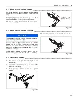
Page 42: ...ength of the reel when the paper is held at 90 to the bedknife Figure 9C 9 4 CUTTING HEIGHT _________________________________________________________ Note Always make the reel to bedknife adjustment b...

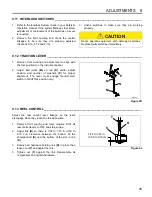
Page 43: ...ce no end play between components Continue to tighten nut until next slot in nut aligns with hole in bedknife adjuster rod T Install new cotter pin Check torque required to rotate adjuster rod T Maxim...

Page 44: ...se to the floorboard check the amount of brake lining left a Replace lining b Adjust nut F to obtain a distance of 3 5 16 in 8 4 cm between rod pivot points when brakes are new and to compress spring...

Page 45: ...position and number of washers P for proper alignment The lever must engage Neutral start switch in NEUTRAL position only Figure 9K 9 13 REEL CONTROL___________________________________________________...

Page 46: ...bove the ground If they are not level with the ground adjust torsion spring Z 2 Carefully loosen spring mounting clamp and slowly turn clamp until implement is level Tighten clamp securely Figure 9N 9...

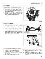
Page 47: ...uld be 7 16 to 9 16 in 1 11 to 1 42 cm 2 Loosen nut V then grip the very end of the cylinder rod close to the adjusting nut point W and turn until spacing is correct Tighten nut V 3 Loosen nut X on th...

Page 48: ...9 ADJUSTMENTS 48 7 Engine drain plug 22 ft lb 29 7 N m...

Page 49: ...Nm 75 8 4 100 11 3 107 12 1 143 16 1 9 16 18 ft lb Nm 92 124 122 165 129 174 172 233 1 4 28 in lb Nm 85 9 6 115 13 0 120 13 5 163 18 4 5 8 11 ft lb Nm 113 153 151 204 159 215 211 286 5 16 18 in lb Nm...

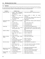
Page 50: ...d bleed fuel lines 2 Interlocks not set before leaving operator s seat 2 Engage parking brake set reel levers to OFF and set traction lever to Neutral before leaving seat Engine overheating 1 Coolant...

Page 51: ...o Bedknife Contact 6 Height of Cut HOC 7 Roller and Roller Bearing Condition 11 2 WASHBOARDING__________________________________________________________ NOTE Arrow indicates direction of travel Washbo...

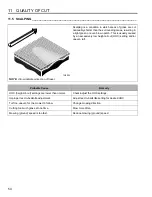
Page 52: ...of varying cutting heights resulting in a wave like cut appearance In most cases the wave tip to tip distance is 2 in 5 cm or less Probable Cause Remedy Mowing ground speed is too fast Reduce mowing g...

Page 53: ...eight of cut settings are different from one side of a reel to the other or from one cutting unit to another Check HOC adjustment of cutting units Worn front roller bearings Check replace front roller...

Page 54: ...even brown patch This is usually caused by an excessively low height of cut HOC setting and or uneven turf Probable Cause Remedy HOC height of cut settings are lower than normal Check adjust the HOC s...

Page 55: ...e Remedy Bedknife improperly adjusted Adjust reel to bedknife setting Dull reel or bedknife cutting edges Sharpen or replace reel blade and bedknife as necessary Mowing ground speed is too fast Reduce...

Page 56: ...or unevenly worn reel Inspect reel Replace as needed Loose or missing bedknife fasteners Check bedknife screws Tighten loose screws replace missing screws Turning too aggressively Cutting units don t...

Page 57: ...posit of clippings concentrated at one end of cutting unit s or between two cutting units forming a line in the direction of travel Probable Cause Remedy Grass is too tall Mow more often Mowing while...

Page 58: ...ife and reel Sharpen or replace reel and bedknife as necessary Missing loose or overtorqued bedknife screws Install replace or tighten bedknife screws to proper torque setting Mowing ground speed is t...

Page 59: ...NOTES 12 59 12 NOTES...

Page 60: ...s Jacobsen Limited West Road Ransomes Europark Ipswich IP3 9TT English Company Registration No 1070731 www ransomesjacobsen com North South America Jacobsen A Textron Company 11108 Quality Drive Charl...

Reviews: