


2 SECONDS INTO CYCLE
*Wash pump starts, runs for 40 seconds, then shuts down. Controlled by C2 cam.
4 SECONDS INTO CYCLE
*Detergent feed pump is energized. The length of time will be field determined. Time will depend on the detergent used and
water conditions. Controlled by C6 cam.
10 SECONDS INTO CYCLE
* Detergent feed pump shuts down. Controlled by C6 cam.
42 SECONDS INTO CYCLE
* Wash pump shuts down. Controlled by C2 cam.
* Drain solenoid is energized (opens). Wash water drains from the unit. Controlled by C3 cam.
51 SECONDS INTO CYCLE
* Fill solenoid valve is energized (opened) starting to fill unit. Controlled by C4 cam.
53 SECONDS INTO CYCLE
* Drain solenoid is de-energized (closed). Controlled by C3 cam.
54 SECONDS INTO CYCLE
* Sanitizer pump is energized, injecting sanitizer into wash tank. Controlled by C5 cam.
* Rinse aid pump is energized, injecting rinse aid into wash tank. Controlled by C7 cam.
58 SECONDS INTO CYCLE
* Sanitizer pump is de-energized. The length of time that the sanitizer pump is activated will be determined in the field.
Timing will depend on the chemical used and water conditions. Controlled by C5 cam.
60 SECONDS INTO CYCLE
* Rinse aid pump is de-energized. The length of time that the rinse aid pump is activated will be determined in the field.
Timing will depend on the chemical used and water conditions. Controlled by C7 cam.
62 SECONDS INTO CYCLE
* Wash pump is energized for the rinse cycle.
* Fill solenoid valve is de-energized.
87 SECONDS INTO CYCLE
* Wash pump is de-energized.
* End of cycle.
PA-1/PA-2 Series Installation & Operation Manual
7610-002-24-11 Rev. J (11/02/2005)
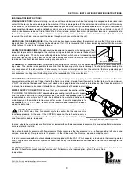
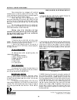
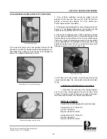
HELPFUL HINT:
Each notch on the cam timer is
equal to 10 degrees or 2-1/2
seconds. For timer adjustment,
use the tool provided which is
taped to the inside of the control box!
17
SECTION 2: INSTALLATION/OPERATION INSCTRUCTIONS
TIMING SEQUENCE (PA-1/PA-2 MODELS)
Summary of Contents for Puritan PA-1
Page 2: ......
Page 7: ...1 SECTION 1 SPECIFICATION INFORMATION ...
Page 14: ...SECTION 2 INSTALLATION OPERATION INSTRUCTIONS 8 ...
Page 24: ...18 SECTION 3 PREVENTATIVE MAINTENANCE ...
Page 26: ...20 SECTION 4 TROUBLESHOOTING ...
Page 31: ...25 SECTION 5 SERVICE PROCEDURES ...
Page 38: ...THIS PAGE IS INTENTIONALLY LEFT BLANK 32 ...
Page 39: ...33 SECTION 5 PARTS SECTION ...
Page 70: ...SECTION 6 ELECTRICAL SCHEMATICS 64 ...
Page 75: ......