


10
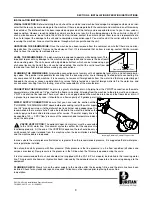
ELECTRICAL POWER CONNECTION:
Electrical and grounding connections must comply with the applicable portions of the
National Electrical Code ANSI/NFPA 70 (latest edition) and/or other electrical codes.
Disconnect electrical power supply and place a tag at the disconnect switch to indicate that you are working on the circuit.
The dishmachine data plate is located on the right side and to the front of the
machine. Refer to the data plate for machine operating requirements, machine
voltage, total amperage load and serial number.
To install the incoming power lines, open the control box. This will require unlock-
ing the control box cover. While unpacking the unit, the keys will be located on
the back of the unit tie-wrapped to the plumbing. Install 3/4” conduit into the pre-
punched holes in the back of the control box. Route power wires and connect to
power block and grounding lug. Install the service wires (L1 & L2) to the appro-
priate terminals as they are marked on the terminal block. Install the grounding
wire into the lug provided. Tighten the connections. It is recommended that “DE-
OX” or another similar anti-oxidation agent be used on all power connections.
VOLTAGE CHECK:
Ensure that the power switch is in the OFF position and
apply power to the dishmachine. Check the incoming power at the terminal block
and ensure it corresponds to the voltage listed on the data plate. If not, contact a
qualified service agency to examine the problem. Do not run the dishmachine if
the voltage is too high or too low. Shut off the service breaker and mark it as being
for the dishmachine. Advise all proper personnel of any problems and of the loca-
tion of the service breaker. Close and lock the control box cover.
PA-1/PA-2 Series Installation & Operation Manual
7610-002-24-11 Rev. J (11/02/2005)
SECTION 2: INSTALLATION/OPERATION INSTRUCTIONS
ELECTRICAL INSTALLATION INSTRUCTIONS
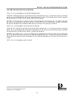
Lower Control Box - Incoming Power Connection
Power Block
Ground Lug
Summary of Contents for Puritan PA-1
Page 2: ......
Page 7: ...1 SECTION 1 SPECIFICATION INFORMATION ...
Page 14: ...SECTION 2 INSTALLATION OPERATION INSTRUCTIONS 8 ...
Page 24: ...18 SECTION 3 PREVENTATIVE MAINTENANCE ...
Page 26: ...20 SECTION 4 TROUBLESHOOTING ...
Page 31: ...25 SECTION 5 SERVICE PROCEDURES ...
Page 38: ...THIS PAGE IS INTENTIONALLY LEFT BLANK 32 ...
Page 39: ...33 SECTION 5 PARTS SECTION ...
Page 70: ...SECTION 6 ELECTRICAL SCHEMATICS 64 ...
Page 75: ......