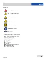


10
07610-003-78-18-N
All electrical ratings provided in this manual are for reference only. Always refer to the machine data plate to get the exact
electrical information for this machine.
All electrical work performed on machines should be done in accordance
with applicable local, state, territorial, and national codes
. Work should only be performed by qualified electricians and
authorized service agents. A list of authorized Service Agencies is located in the back of this manual.
Note that all electrical wiring used in the dishmachine must be rated, at a minimum, for 212 °F (100 °C), and that only
copper conductors must be used.
Where applicable, heating element amperage draws have been adjusted for the assumed input voltage. The manufacturer
assumes incoming voltages will be either 208, 230, or 460 Volts. Some of the heating elements used in our machines are
actually rated for other voltages, such as 240 or 480 Volts. Always verify the amperage draw of the machine in operation
when sizing circuit protection.
If the machine is equipped with the optional rinse heater, note the rinse heater has its own electrical connection and
therefore requires a separate service. Amperage loads for motors and heaters are called out on the machine data plate
for the installation/service technician.
The electrical configurations of the machines are as follows:
Available Electrical Characteristics:
•
208 V, 60 Hz, Single-phase
•
230 V, 60 Hz, Single-phase
•
208 V, 60 Hz, Three-phase
•
230 V, 60 Hz, Three-phase
•
460 V, 60 Hz, Three-phase
Available Wash Tank Heaters:
• 15 kW (standard for CREW 44)
• 18 kW (optional for CREW 44, standard for CREW 66)
Available Electrical Characteristics:
• None (standard)
• 12 kW (40
°
F rise in temperature)
• 18 kW (70
°
F rise in temperature)
ELECTRICAL REQUIREMENTS
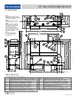
SPECIFICATIONS
i
Summary of Contents for crew series
Page 2: ......
Page 6: ......
Page 81: ...72 07610 003 78 18 N STEAM BOOSTER HEATER SCHEMATICS...
Page 84: ...75 07610 003 78 18 N 208 230 460 VOLT 60 HZ 3 PHASE 44 ELECTRICALLY HEATED SCHEMATICS...
Page 85: ...76 07610 003 78 18 N 208 230 VOLT 60 HZ 1 PHASE 44 ELECTRICALLY HEATED SCHEMATICS...
Page 86: ...77 07610 003 78 18 N 208 230 460 VOLT 60 HZ 3 PHASE 44 STEAM HEATED SCHEMATICS...
Page 87: ...78 07610 003 78 18 N 208 230 VOLT 60 HZ 1 PHASE 44 STEAM HEATED SCHEMATICS...
Page 88: ...79 07610 003 78 18 N 208 230 460 VOLT 60 HZ 3 PHASE 66 ELECTRICALLY HEATED SCHEMATICS...
Page 89: ...80 07610 003 78 18 N 208 230 VOLT 60 HZ 1 PHASE 66 ELECTRICALLY HEATED SCHEMATICS...
Page 90: ...81 07610 003 78 18 N 208 230 460 VOLT 60 HZ 3 PHASE 66 STEAM HEATED SCHEMATICS...
Page 91: ...82 07610 003 78 18 N 208 230 VOLT 60 HZ 1 PHASE 66 STEAM HEATED SCHEMATICS...
Page 92: ...83 07610 003 78 18 N BLOWER DRYER 240V SCHEMATICS...
Page 93: ...84 07610 003 78 18 N BLOWER DRYER 480V SCHEMATICS...


