ProTIG 500 AC/DC
Operating Manual
Page 37
28. Welding torch cooling (Option)
Maximum pressure: 3,3bar
Way of functioning
The circulation water cooling is based on the function of a recooling plant:
the cooling liquid is cooled down to approximately room temperature via heat
exchanger, with the help of the room air which is circulated by the fan.
Water-cooled torch
The torch is cooled by a built-in low-noise, pump operated, water-cooling system.
The water tank should be kept almost full. In case of loss of water due to
exchange of torch or hose sections, Check water level in the tank.
Water flow monitoring
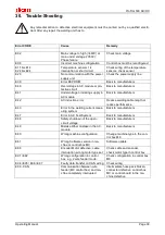
If there is too less water pressure, a sensor turns off the control and display the error message ‚E01.
After the cause is corrected for the water deficiency, the machine must switch off and on.
5
- ONLY use JÄCKLE coolant JPP (Order No. 900.020.400)
- Unsuitable coolants can cause property damage and loss of warranty.
- Do not mix with water or other coolant.
- Do not weld without cooling water! Tank must always be full.
- Pump must not run dry, not even for a short time. Deaerating the pump.
- Hazardous to health – keep away from children!
MATERIAL SAFETY DATA on
www.jaeckle-sst.de
available.
- Frost-resistance up to -30°C
29. Remote control socket
Pin
Name
Description
A / 1
Actual volt-
age
(U-actual)
Output signal between 0V and +10 V.
The ratio between welding voltage and signal voltage is 10:1.
Example: 40V welding voltage = 4.0V signal voltage
Input impedance should be
≥
10k. The reference potential is pin 3
B / 2
Actual cur-
rent
(I-actual)
Output signal between 0V and +10 V.
The ratio between welding current and signal voltage is 100:1.
Example: 100A welding current = 1V signal voltage
Input impedance should be
≥
10k. The reference potential is Pin 3
C / 3
GND
Ground potential for Pin 1, 2, 4, 5
D / 4
Master (U)-
voltage 2
Input signal for the function of EC 2
1) To contact a potentiometer (between pin 3 (0V) and pin 6 (+10 V)).
The output of the potentiometer changes this value.
2) Similarly, a control voltage between 0 V and a maximum of +10 V can be applied
(reference point Pin 3).
E / 5
Master (U)-
voltage 1
Input signal for the function of EC 1
1) To contact a potentiometer (between pin 3 (0V) and pin 6 (+10 V)).
The output of the potentiometer changes this value.
2) Similarly, a control voltage between 0 V and a maximum of +10 V can be applied
(reference point Pin 3).
F / 6
+10V
+10V reference voltage output for potentiometer control Pin 4, 5
The maximum output current is 10mA.
G / 7
+24V
+24V reference output voltage for the switch signals Pin 8, 9, 10
The maximum output current is 10mA
H / 8
T – BT
MIG / TIG torch trigger input signal, supply to pin 7
Start signal for automation.
J / 9
T – up
Input signal for an up / down torch, here the increasing (up) signal, supply to pin 7
K / 10
T – down
Input signal for an up / down torch, here the decreasing (down) signal, supply to pin
7
L / 11
Current flow
Potential-free contact. If a current flow is detected, the contact is closed.
The contact opens when the current flow is interrupted.
Maximum voltage 48V, maximum current 1A
M / 12
Current flow
13-17
free
Not used!
More information’s are shown in the circuit diagram.


