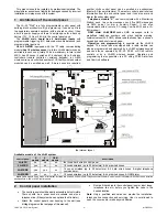
JA-63 „PROFI“ Alarm System
- 10 -
MGK55401
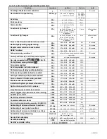
9.3 Exit
delay
sequence: 2 0 x
To change the duration of the exit delay enter:
20x
(where
x
represents time in seconds x10). The delay can be selected
from 10 to 90 seconds.
Example: to select an Exit delay duration of 20 seconds,
enter
202
Factory default setting:
30 seconds
9.4 Entrance
delay
sequence: 2 1 x
To change duration of the entrance delay enter:
21x
(where
x
represents time in seconds x10). The delay can be selected
from 10 to 90 seconds.
Example: To select entrance delay duration of 40 seconds,
enter
214
Factory default setting
: 30 seconds
9.5
Alarm duration
sequence: 2 2 x
The alarm duration can be selected from 1 to 8 or 15 minutes
entering:
22x
(where
x
=time in minutes for1 to 8, x=9 means 15
minutes and x=0 means 10 seconds)
Example: to select an alarm duration of 15 minutes, enter 229
Factory default setting:
4 minutes
9.6
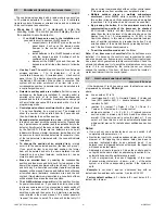
PgX and PgY output functions
sequences: 2 3 x & 2 4 x
The control panel
outputs PgX and PgY can
have different functions,
depending on parameter
x
in the corresponding
sequence:
23x
- determines trigge-
ring of
PgX
24x -
determines trigge-
ring of
PgY
where:
x
represents the following functions (non split system):
0 Chime
– triggered during the entrance delay (pre-alarm
output)
1 Fire
– triggered by a fire alarm (by a smoke or a gas
detector)
2 Arm
– activated when the control panel is armed
(complete & partial arming)
3 Panic
– activated when a silent panic alarm is triggered
4 Alarm
– triggered by any audible alarm (except panic
alarm)
5 Door
– activated for 5sec. after
(F3) entering
(electric door lock opening)
6 Home
– activated when the control panel is partially armed
(Home arming)
7 No AC
– triggered by an AC power failure
8 Phone/F8
– output can be operated
remotely by phone
or by SMS (if this feature is supported by installed
communicator) or locally
from the keypad
by F81 (ON)
and F80 (OFF). If a code is requested to operate the
system (see 9.13) then the F8x instruction should be
followed by a valid user code.
Note: the control panel also wirelessly transmits the PgX and PgY
signals. Wireless output modules UC-216 and UC-222 can be used
to receive the signals (see 9.12). The function of the UC module
output relays is determined by the 23x and 24x setting.
Example: the PgX will work as a Panic output when 233 is
entered, PgY as Door output when 245 is entered.
Factory default setting:
PgX=Chime, PgY=Arm
9.7
Recorded message and phone number editing
in the user mode
sequence:
2 5 x
The
U
ser mode, which is accessible with F 0 “Master Code”, is
for bypass setting, system testing and battery replacement. This
setting enables the user to change the voice message and
telephone numbers of the built in dialer. If the changes are
enabled, then programming sequences for number
programming, voice message recording and dialer testing are
accessible in the
U
ser mode. These settings have effect only
when the control panel has a telephone communicator module.
options:
2 5 1
changes
enabled
2 5 0
changes
disabled
(no dialer programming in
the
U
ser mode)
Factory default setting:
changes disabled
9.8
Radio signal jamming testing
sequence: 2 6 x
When this function is enabled, the control panel will indicate
trouble if the working band is jammed for more than 30 seconds.
Jamming will trigger an alarm when the control panel is armed.
Do not enable this testing if the control panel does not have a
radio module.
options:
2 6 1
testing
enabled
2 6 0
testing
disabled
Note: in large cities and some other locations the system can be
randomly jammed from time to time (near TV or radio station,
GSM cell station etc.). In these cases the control panel can work
without any problems because all important data is repeated, but
the jamming test should not be enabled. The level of the signals
and interference can be observed using the Comlink software
(see 12)
Factory default setting:
disabled
9.9 Regular communication checking
sequence:
2 7 x
The control panel will check communication regularly with all
enrolled items (detectors, keypads, siren etc.) when this function
is enabled. If communication is lost with any item, the control
panel will indicate the fault of this item (when armed reaction of
the system depends on setting 696x, see 9.28). Do not enable
this checking if the control panel does not have a radio module.
options:
2 7 1
checking
enabled
2 7 0
checking
disabled
Note: in large cities and some other locations with a strong radio
interference the communication can be jammed randomly. The
control panel can detect such a strong interference as a
temporary loss of communication with an item. Even in this
case, the system is usually able to work without any problems
because all important data is repeated, but the communication
check should not be used.
Factory default setting:
checking disabled
If the system is split:
x
23x
(PgX)
24x
(PgY)
0
Alarm A
Alarm A
1
Alarm B
Alarm B
2
Chime A
Chime A
3
Chime B
Chime B
4
Arm A
Arm B
5
Door A
Door B
6
Panic A
Panic B
7 FIRE
No
AC
8 Phone/F8
Phone/F8
Summary of Contents for JA-63 PROFI"
Page 1: ...JA 63 PROFI Alarm system installation manual...
Page 2: ......


