


JABLOTRON FUTURA
INSTALLATION MANUAL
19/43
JABLOTRON LIVING TECHNOLOGY
T a b l e n o . 2
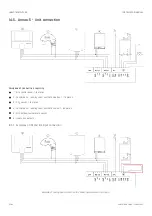
T a b l e n o . 2 – button DIP switch
T h e f i r s t t h r e e s w i t c h e s h a v e t o b e s e t f o r t h e c o r r e s p o n d i n g z o n e (s h o w n z o n e n o . 1 , s a m e a s i n F i g . 2 5 ).
T h e f i r s t t h r e e s w i t c h e s h a v e t o b e s e t f o r t h e c o r r e s p o n d i n g z o n e (s h o w n z o n e n o . 1 , s a m e a s i n F i g . 2 5 ).
First column (switch no. 4) shows button address.
Second column (switch no. 5) shows that the button is set as a s w i t c h
s w i t c h (ON until pressed again).
Third column (switch no. 6) enables the use of a terminating resistor.
①
②
①
②
①
②
# 2
Figure 26 – Example of a button configuration: two buttons, **switch** mode, terminating resistor enabled


