background image


24 

MAIL-IN SERVICE 

When shipping the unit carefully pack and send it prepaid, adequately insured and preferably 
in the original carton. Include a letter detailing the complaint and provide a day time phone 
and/or email address where you can be reached. 


LIMITED WARRANTY LIMITS AND EXCLUSIONS


1)


This Limited Warranty ONLY COVERS failures due to defects in materials or workmanship, 

and DOES NOT COVER normal wear and tear or cosmetic damage.   
The Limited Warranty ALSO DOES NOT COVER damages which occurred in shipment,   
or failures which are caused by products not supplied by warrantor, or failures which result from   
 
 
accidents, misuse, abuse, neglect, mishandling, misapplication, alteration, faulty   
 
installation, set-up adjustments, misadjustment of consumer controls, improper maintenance, power 
line surge, lightning damage, modification, or service by anyone other than a Factory Service center 
or other Authorized Servicer, or damage that is attributable to acts of God. 
2)


THERE ARE NO EXPRESS WARRANTIES EXCEPT AS LISTED UNDER "LIMITED 

WARRANTY COVERAGE". THE WARRANTOR IS NOT LIABLE FOR INCIDENTAL OR 
CONSEQUENTIAL DAMAGES RESULTING FROM THE USE OF THIS PRODUCT, OR 
ARISING OUT OF ANY BREACH OF THIS WARRNTY. (As examples, this excludes damages 
for lost time, cost of having someone remove or re-install an installed unit if applicable, travel to 
and from the service, loss of or damage to media or images, data or other recorded content. The 
items listed are not exclusive, but are for illustration only.) 
3)


PARTS AND SERVICE, WHICH ARE NOT COVERED BY THIS LIMITED WARRANTY, 

ARE YOUR RESPONSIBILITY. 

Summary of Contents for JTECH-4K88-EX2

Page 1: ...1 Website www jtechdigital com Toll Free 1 888 610 2818 Email support jtechdigital com USER MANUAL J Tech Digital HDMI 4K 60HZ 4 4 4 Matrix Extender Model JTECH 4K88 EX2 JTD ID 495...

Page 2: ...n Off setting Default OFF 10 3 Reboot setting 11 4 Factory setting 11 4 5 INFO mode Interface 12 5 Application Diagram 13 6 Remote Control Description 14 7 IR system 14 8 Command Control 15 9 Web Cont...

Page 3: ...0HZ 60HZ input 2 Package Contents 1 1x Main Unit HDBaseT Matrix and 7x Receivers 2 1x Power Cable 3 1x Remote control 4 16xIR Transmitter cables 16x Wide Band IR Receiver cables 5 1x CD for control so...

Page 4: ...N LOCK ENTER DSP OFF Short press output N then press DSP OFF to turn off the output Long press Output 8 to select all output then press DSP OFF to turn off all the output AC 100 240V power port IR in...

Page 5: ...y press the number key such as the output channel 5 select the key 5 and press it again to cancel the selection Long press output channel 8 to select all channels and long press again to cancel MENU F...

Page 6: ...Operation format output channel input channel For Example Output port 2 5 8 switch to input 7 Operation Press OUT number 2 5 8 IN number 7 to complete the switch 4 2 2 Video Control The video interfa...

Page 7: ...L GT_ U ZV Z OJKU UX GRR U ZV ZY OJKU 9KRKIZ OJKU OT ZNK SKT GTJ VXKYY 4 8 NKT YK 6 5 4 H ZZUT ZU YKRKIZ 5T 5LL 6XKYY 4 8 KTZKX TK Z VGMK 6XKYY 6 5 4 H ZZUT ZU YKRKIZ ZNK U ZV Z NK TOTZN VUXZ SKGTY 22...

Page 8: ...follows Audio interface can be set to output Audio Analog or SPDIF then choose Audio output or mute Operating instructions Select Audio from the main menu and press ENTER to confirm Press the up and...

Page 9: ...et each input s EDID Include Default EDID User EDID Copy EDID Copy HDBT EDID Specific operations are as follows 9KRKIZ OT ZNK SKT GTJ VXKYY 4 8 NKT YK 6 5 4 H ZZUT ZU YKRKIZ ZNK OTV Z NK T SKGTY 22 OT...

Page 10: ...00 9600 19200 38400 57600 115200 Default Baud Rate is 115200 9KRKIZ 9KZ V OT ZNK SKT GTJ VXKYY 4 8 NKT YK 6 5 4 H ZZUT ZU YKRKIZ ZNK GTJ VXKYY 4 8 6XKYY 6 5 4 H ZZUT ZU YKRKIZ ZNK HG J XGZK GTJ VXKYY...

Page 11: ...UT ZU YKRKIZ ZNK 8KHUUZ GTJ VXKYY 4 8 6XKYY 6 5 4 H ZZUT ZU YKRKIZ 4U UX KY GTJ VXKYY 4 8 ZU IUTLOXS Reboot setting P9 4 Factory setting 9KRKIZ 9KZ V OT ZNK SKT GTJ VXKYY 4 8 NKT YK 6 5 4 H ZZUT ZU YK...

Page 12: ...12 Operating Instruction 4 5 INFO mode Interface Check the device information IP or System information INFO mode P11...

Page 13: ...13 Operating Instruction 5 Application Diagram...

Page 14: ...on UP and DOWN button Enter button 7 IR system The matrix can pass the IR signal through the IR system to the HDMI source or pass the IR signal from the HDMI source to the HDMI sink Dual way IR using...

Page 15: ...w and install the RS232 software on the computer Enter the main interface of the software as shown in the figure below In the parameter configuration area the serial number of serial port and PC conne...

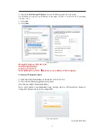
Page 16: ...mand list for details Example Output5 switch to input 6 channel off Operation format video_d out5 matrix 6 onoff 0 9 Web Control 9 1 Change the IP address of your PC 1 Connect the Ethernet port of mat...

Page 17: ...t IPAddress 192 168 1 168 MASK 255 255 255 0 Gateway 192 168 1 1 MAC 0008 DCCA CF3F Each device have different MAC address 9 2 Enter Web and Control 1 Enter the default IP address of the matrix 192 16...

Page 18: ...ort message LCD display To ensure network connectivity enter IP address in the browser address bar and click to enter the login interface Enter the correct account number and password to enter the int...

Page 19: ...me of modification in the new name column and click Save Exit Web control P22 AUDIO interface description 1 Represents the output audio You can only choose to output all or mute all 2 Just click the i...

Page 20: ...KLG RZ 1 8 KLG RZ 1 8 26 3 KLG RZ 1 26 3 KLG RZ 1 26 3 KLG RZ 6 26 3 Blue means selected Web control P23 User EDID uesr1 8 means the user s EDID A total of 8 EDID can be saved Copy EDID HDMI01 01 mean...

Page 21: ...roll bar to modify System interface description The user name means change the logged in user name New password means enter the new password in the login interface enter the new password again to conf...

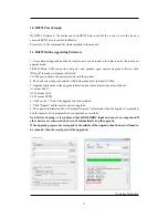
Page 22: ...tting is consistent with the host baud rate default 115200 5 Upgrade instructions in the upgrade instruction box some instructions are as follows A1 means MCU A1 01 means GUI F0 01 means HTML 6 Click...

Page 23: ...electric shock or other Hazards 4 Safety check After repairs or service ask the servicer to perform safety checks to confirm that the unit is in proper working condition WARRANTY If your product does...

Page 24: ...y installation set up adjustments misadjustment of consumer controls improper maintenance power line surge lightning damage modification or service by anyone other than a Factory Service center or oth...

Reviews: