M
AINTENANCE
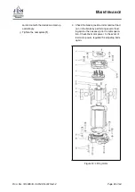
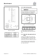
Figure 19: Lifting motor
2. Checking vane wear: When the vanes
(7)
are
worn, the engine power is reduced. Replace
the vanes
(7)
and starting aids
(8)
together.
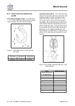
Figure 20: Vane
Vane dimensions after maximum permissible
wear (measured at the thinnest point):
L
H
T
109,1 mm
35,0 mm
5,4 mm
3. Check the braking surfaces of the brake pis-
ton
(5)
and the cover with brake lining
(13)
for
wear and damage: If the braking surfaces are
damaged or worn, the brake piston
(5)
or the
middle part half with the brake lining must be
replaced:
a) The circular wear pattern in the brake
surfaces must not be deeper than
0.02mm:
The extremely low-wear braking material
will not reach the wear limit of 0.02mm
within the design-dependent service life
of the hoist, under intended use. Should
the wear limit be reached prematurely,
the actual compressed air pressure must
be checked with the device switched on
(the brake drags in the event of insuffi-
cient pressure).
4. Engine assembly with additional basic lubrica-
tion of the engine:
a) Provide the braking surface and rotor
bearing (needle bush) of the cover with
the brake pad with a thin layer of high-
performance lubricant.
b) Coat the internal cylinder of the motor
housing lightly with high-performance
grease
c) Coat the entire rotor lightly with high-
performance grease and insert into the
front rotor bearing with the clutch side
first.
Doc.-No.: VA049318-10-OM-EN-0319-64-2
Page
57
of 64

