Support: 855-473-7449 or 408-943-4100 Email:
Page 8
5 Racking the R10, R20, or R40
The R10, R20, and R40 share the same rail kit and racking process. Because each system has slightly different di
-
mensions, it is recommended to double check the rack rail placement for the purchased system.
Drives should only be installed in a system after it has been placed in the rack. It is also recommended to remove all
installed drives
before
unracking a system.
Always
team-lift
a system when installing to a rack.
5.1 Rack Requirements
5.2 Attach the Chassis Rails
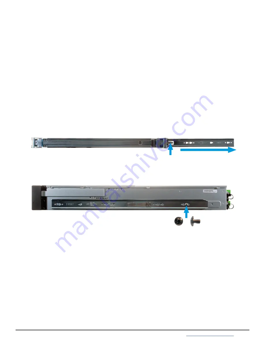
Each rail has two components, the outer rack rail and the inner chassis rail. To protect it during shipping, the chassis
rail is inserted into the rack rail and must be removed before attaching to a system. Slide the chassis rail forward
until the metal catch stops it in place. Push in the catch and continue to slide the chassis rail forward until it is free
of the rack rail.
PUSH
SLIDE
Take the chassis rail and align the end stamped “FRONT” with the front of the system. Fit the rail keyholes over the
mounting pegs on the side of the system and slide it into place. Use one of the included short M4 screws to secure
the rail to the system.
The image shows attaching the rail to an R20, but the R10 and R40 follow the same procedure. For the R20 and R40,
use the screw hole at the back of the chassis for securing the rail. Follow this procedure to slide out and attach the
second chassis rail to the other side of the system.
The R10, R20, or R40 requires an EIA-310 compliant rack. To properly install the rack rails, the front and rear vertical
rack posts need to be spaced between
23” - 35.75” (584mm-908mm)
apart.
Short M4 Screw


