background image

Suspended Configuration

GS Series

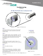
Cord ran through 

penetration fitting 

and cord seal.

Chain and Kellum 

Grip attached to 

quick link on 

penetration fitting

Mixer suspended 

near tank floor

Chain Connected 

to Mixer

Suspended Configuration

The suspended configuration is primarily used 

on tanks without a flat bottom. This method of 

installation is different with aluminum roofs or 

geodesic domed roofs. 

Installation Procedures


Step 1:

Attach the retrieval chain to the GS mixer at the 

pre-located quick link. Tighten the quick link with 

a wrench/pliers. Plan out a safe procedure and 

hoist the GS Mixer to the top of the tank near the 

hatch opening. Use the chain and submersible 

cable attached to the GS Mixer for lifting and 

supporting the weight. Keep clear of chain and 

electric cord to avoid entanglement.

Step 2:

Tie off the tail end of the retrieval chain and 

electric cord strain relief to the quick link at the 

bottom of the tank penetration fitting. 

Step 4:


Pull the retrieval chain up until it is taught, then 

mark off the desired distance the GS Mixer is to 

be suspended above the floor, placing the quick 

link that desired distance down the retrieval 

chain below the tank penetration fitting.

Step 5:

Slowly pull up the GS Mixer and connect the 

quick link to the tank penetration fitting.

IMPORTANT

It is important to disinfect all components in

contact with potable water. A common practice is to 

use a minimum 200ppm chlorine or alternate dis-

infectant solution in water to spray all components 

that will contact the drinking water. There may be 

additional  decontamination  procedures  required, 

so  it  is  important  to  understand  what  procedures 

are  acceptable.    Decontamination  should  be  per-

formed right before the unit is lowered through the 

hatch.  The  mixer  should  be  immersed  in  water 

shortly  after  having  been  decontaminated  to  pre-

vent corrosion caused by contact with chlorine or 

alternate disinfectant.

© 2020 Ixom | www.medoraco.com | 866 - 437 - 8076 | [email protected]

Placement

1916_10006_20200514

O&M_GS9_10012_20200811 - 10

Summary of Contents for Medora GridBee GS-9

Page 1: ...2020 Ixom www medoraco com 866 437 8076 info medoraco com O M_GS9_10012_20200811 GridBee GS 9 Single Phase Operation Maintenance Manual...

Page 2: ...Processes Ixom equipment continues to be at the forefront as the 1 world leader for in situ water body treatment 2020 Ixom www medoraco com 866 437 8076 info medoraco com Table of Contents 10014_2020...

Page 3: ...pment You can avoid hazards by following these safety instructions and applying some ordinary common sense when operating or servicing this unit Keep in mind that full operator attention and alertness...

Page 4: ...entative ELECTRICAL HAZARD WARNING THIS EQUIPMENT CONTAINS HIGH VOLTAGE ELECTRICAL SHOCK CAN CAUSE SERIOUS OR FATAL INJURY ONLY QUALIFIED PERSONNEL SHOULD ATTEMPT PLACEMENT OPERATION AND MAINTENANCE O...

Page 5: ...mply with all relative OSHA and local regulations while installing and performing any maintenance to the mixer circulation equipment Key OSHA Compliance Standards that must be followed and not limited...

Page 6: ...rain Relief Cord Fixture GS Core Unit 75 or 150 Electric Cord Not Pictured 75 or 150 Stainless Steel Chain Top of Tank Junction Box Cord Seal 2020 Ixom www medoraco com 866 437 8076 info medoraco com...

Page 7: ...6 7 9 910 9 8 1120 1 4 2 0 42 54 99 99 28 H Service Entrance to Motor Maximum Length In Feet Based on Service Factor Amps and 5 Voltage Drop Motor Rating 60 C and 75 C Insulation AWG Copper Wire Size...

Page 8: ...to protect from corrosion 7 Strain Relief Washer 8 Quick link for connecting retrieval chain and kellem grip to strain relief washer 9 Kellem grip to support cable weight and to provide strain relief...

Page 9: ...oxy Follow concrete epoxy manufacture s preparation and installation guidelines 7 A 3 4 dia minimum to 1 1 4 dia maximum hole drilled through hatch neck for electrical cord 8 Junction box mounted to e...

Page 10: ...pport I beam 9 Quick link 10 Kellem grip 11 A 1 5 16 dia hole drilled through panel and sealed with Lexel Locate penetration within arms reach of an access point 12 Eyebolt drilled through support I b...

Page 11: ...ugh cord seal Locate power source receptacle and flex con duit termination at customer preferred location of mixer control panel Terminate conduit using flex conduit with male thread end for panel mou...

Page 12: ...bottom of the tank penetration fitting Step 4 Pull the retrieval chain up until it is taught then mark off the desired distance the GS Mixer is to be suspended above the floor placing the quick link...

Page 13: ...ank However the mixer should stay clear at least 10 15ft away from a common inlet outlet pipe Radial Orientation It is best to orientate the mixer so the discharge slots are radial with the tank This...

Page 14: ...each splice individually sealed to protect from corrosion Top of tank Junction Box Not applicable for GS 12 Air Is the field wiring correct Requirements Is the mixer submerged with at least 2 0 75m of...

Page 15: ...ve probe on the black wire and the negative probe on the white wire that were disconnected 6 Record the reading Depending on the length and gauge of wires to the mixer the ohms should be approximately...

Page 16: ...r build up You should be able to move the impeller freely with no resistance See Figure 2 Step 4 Remove any debris if necessary Step 5 Place the white end plate back on the GS Mixer ensuring to line u...

Page 17: ...rication schedule required Automatic reset on winding thermal overload protection and surge arresters built in Mounted in flow sleeve for superior cooling and long motor life in submerged temperatures...

Page 18: ...d and provided with the purchased equipment is the valid warranty GridBee control panels cold weather hose kits air compressors and any optional accessories These items are considered buyout items for...

Page 19: ...on and other related subjects as required by OSHA to perform the necessary work to install or remove SolarBee and GridBee equipment and are knowlegeable in the regulations and standards of OSHA If you...

Reviews: