background image

Hose / Strainer

 - The hose is directly below the distributor dish and the strainer is located at the end of 

the hose.  The strainer contains a buoyant float ball inside that allows the strainer to draw water from 
approximately 1.5 ft to 2 ft (0.45m to 0.6m) above solid bottom.  The hose is designed to make a "J" shaped 
bend at the bottom so that the strainer does not draw sediment up from the bottom.  The strainer has a chain 
connected to it and can be chained up at more shallow depths if necessary.  The chain also is used for pulling 
up the strainer to check it for plugging.  

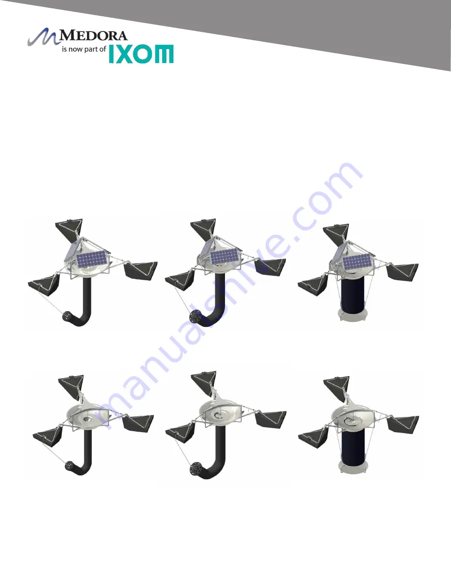
Hose and Strainer Configuration - MODEL MAY VARY

SB2500

SB10000

SB5000

GF2500

GF10000

GF5000

© 2020 Ixom | www.medoraco.com | 866 - 437 - 8076 | [email protected]

Features

Features

SB and GF Large Frame Mixers

10267_20200220

O&M_GF10000_10492_20201020 - 10

Summary of Contents for GridBee GF10000

Page 1: ...2020 Ixom www medoraco com 866 437 8076 info medoraco com O M_GF10000_10492_20201020 GridBee GF10000 Owner s Manual...

Page 2: ...ewater Treatment Processes Ixom equipment continues to be at the forefront as the 1 world leader for in situ water body treatment 2020 Ixom www medoraco com 866 437 8076 info medoraco com Table of Con...

Page 3: ...ent You can avoid hazards by following these safety instructions and applying some ordinary common sense when operating or servicing this unit Keep in mind that full operator attention and alertness a...

Page 4: ...tative ELECTRICAL HAZARD WARNING THIS EQUIPMENT CONTAINS HIGH VOLTAGE ELECTRICAL SHOCK CAN CAUSE SERIOUS OR FATAL INJURY ONLY QUALIFIED PERSONNEL SHOULD ATTEMPT PLACEMENT OPERATION AND MAINTENANCE OF...

Page 5: ...ly with all relative OSHA and local regulations while installing and performing any maintenance to the mixer circulation equipment Key OSHA Compliance Standards that must be followed and not limited t...

Page 6: ...providing gentle mixing de stratification and surface renewal The GF series GridBee requires a minimal amount of AC grid power The grid provides power to the onboard AC DC power box and motor controll...

Page 7: ...km hr wind higher than 4 ft 1 2m waves or ice thaw it is possible for the duckbill anchors to pull partly or completely out of the ground or the tether cable span across the pond to break loose from...

Page 8: ...roller and brushless motor the two components need to be located close to one another This is the primary reason for having the motor controller located directly on the Machine All electronic connecti...

Page 9: ...aft coupling connects the brushless motor drive shaft to the impeller shaft The shaft coupling is located directly below the brushless motor and is made up of 3 main components These components are ca...

Page 10: ...water should freeze around the machine the freeze sleeve will stand still frozen in by the ice but inside the plastic sleeve the impeller shaft will be turning The impeller blades are welded to a hub...

Page 11: ...tering the machine and the upper water layer leaving the dish The top lip of the distributor dish is set from 3 4 inch to 2 5 inches 2 cm to 6 4 cm Please refer to the table below for exact settings b...

Page 12: ...haped bend at the bottom so that the strainer does not draw sediment up from the bottom The strainer has a chain connected to it and can be chained up at more shallow depths if necessary The chain als...

Page 13: ...nts without being damaged The turnbuckle is self locking Simply rotate the handle to expand or collapse the turnbuckle for dish depth adjustment It is important to check the distributor dish depth rou...

Page 14: ...lyethylene The floats are filled with a Polystyrene closed cell foam for long term buoyancy The floats have a uniquely designed shape to Minimize the interference with the water flow on the surface co...

Page 15: ...ise the float up fitting it into the float arm Use the float pins to secure the float to the float arm STEP 5 Place hairpins in each float pin to secure it and prevent the pin from coming out STEP 6 R...

Page 16: ...DURING FINAL SETTINGS AND UNIT WOULD HAVE TO BE PULLED BACK OUT OF THE WATER CORRECTED AND RE INSTALLED SB10000 WITH 15FT 4 5m OR LESS HOSE SB 7500 20FT 4 5m OR LESS HOSE ALL SB5000 ALL SB2500 ALL PO...

Page 17: ...y STEP 3 Take the float arm and slip the narrow end with Float Arm Stems around the core unit leg Align the holes through the Float Arm Stems with the correct float arm connection hole determined from...

Page 18: ...t of the turnbuckle assembly is in place take the opposite end of the turnbuckle and slide it into the float arm assembly as shown in picture STEP 5 Align the hole through the shaft with the float arm...

Page 19: ...dish STEP 3 Place one of the chain brackets over the square tubing with the wider side facing up and the opening facing outward STEP 4 Once the chain bracket is slid around the square tubing insert t...

Page 20: ...4 Fasten the leg extension to the Core unit assembly using a set of two 5 16 inch x 2 inch 8mm x 51mm clevis pins STEP 5 Secure both pins using two hair pins STEP 6 Repeat steps 2 through 5 for each...

Page 21: ...sing a pliers STEP 4 Find the last link on the end having the lowest numbered indicator This link should attach to the welded link located directly below the chain bracked on the hose flange connected...

Page 22: ...s first every time the Machine is inspected or having maintenance procedures performed It is strongly encouraged that anyone working on or near the machine follow these rules Wear a personal floatatio...

Page 23: ...g a three point rigging system connect to all three rigging points of the Machine Hoist the Machine by the three rigging points and slowly lower into the reservoir STEP 3 Tie as much of the hose up as...

Page 24: ...of a nickel or locating the notch on each chain bracket for machines having a hose If using the notch on each chain bracket the water level should be even with the appropriate notch see picture STEP 3...

Page 25: ...l to 1 minute and at least 20 seconds This step is easier with two people one counting revolutions and the other keeping track of the time expired STEP 3 Quit counting revolutions and immediately obse...

Page 26: ...revent it from going through Machine again Follow all local laws and regulations when disposing of any materials collected STEP 4 Observe if there is buildup below the impeller blades If below the imp...

Page 27: ...again Follow all local laws and regulations when disposing of any materials collected STEP 5 Once clean place impeller assembly back in place Slide lower coupling into upper coupling and allow to dro...

Page 28: ...ECTRICAL CONNECTION GRID POWER ONLY 120VAC 60HZ 2 0 AMPS MOTOR CONTROLLER BRUSHLESS DC MOTOR 2020 Ixom www medoraco com 866 437 8076 info medoraco com Electrical Electrical Overview GF Series Large Fr...

Page 29: ...se coupling Wiring Controls Includes power box which converts 120VAC to low voltage DC power Includes submersible SOOW type cable with inhibitors for UV protection SCADA accessory compatible Rotating...

Page 30: ...ID AC POWER OFF BEFORE ENTERING ENCLOSURE GRIDBEE STRONGLY RECOMMENDS THAT AN ELECTRICIAN INSTALL A BREAKER SWITCH OR OTHER TYPE OF SWITCH THAT WOULD DISCONNECT AC POWER GOING INTO THE ELECTRONIC CONT...

Page 31: ...tmeter is available the motor circuit voltage can be measured off terminal blocks 1 and 2 The proper motor voltage should be approximately 45vDC Brain Board voltage should be approximately 12vDC and c...

Page 32: ...DC POWER SUPPLY LED SOLID GREEN LIT SOLID GREEN NOT LIT ERROR CODES 12 VDC ON 12 VDC OFF 12 VDC POWER SUPPLY LED SOLID GREEN LIT SOLID GREEN NOT LIT Source Power Circuit 120 VAC Control Circuit 12 VDC...

Page 33: ...10100 Float 05 PN 18265000 Turnbuckle Assembly 06 PN 100161 Control Box 07 PN 14013022 Motor Control Cord 08 PN 20014500 14 Brushless Motor 09 PN 26023610 36 x 10 Hose 10 PN 26128000 Intake Plate 01 1...

Page 34: ...2020 Ixom www medoraco com 866 437 8076 info medoraco com Dimension Drawing GF10000 1532_10494_20200526 O M_GF10000_10492_20201020 32...

Page 35: ...tear If the factory s service crews performed the original on site placement and startup then this warranty also includes labor Where labor is included in lieu of sending a factory service crew to th...

Page 36: ...and other related subjects as required by OSHA to perform the necessary work to install or remove SolarBee and GridBee equipment and are knowlegeable in the regulations and standards of OSHA If you f...

Reviews: