


17
Step 9. Connect the Speaker
Connect the speaker to the motherboard’s speaker connector. (Normally the red cable is +5V
power)
Step 10. Connect the Power LED
Most computer chassis provides a power LED to identify if the system is on or off. The power LED
lights up when computer is powered on. Connect the power LED to the motherboards’s power
LED connector. (normaly the red cable is +5V power)
Step 11. Connect the IDE LED
This header can be connected to the IDE device LED on front panel.
The LED shows activities of ( read from or write to ) an IDE device.
Step 12. Connect the Power On Button
All the ATX computer chassis provide a power on switch. Connect the header marked “PWR-
ON” to the switch.
Step 13. Connect the Power Supply
This motherboard provides the new 20-pin ATX power connector. Once the ATX power supply is
plugged into this ATX power connector then the poer on connector is necessary to be connected to
wrok as the power On/Off switch.
Step 14. Connect the Keyboard
Follow the keyboard cable’s key direction and connect to this motherboard.
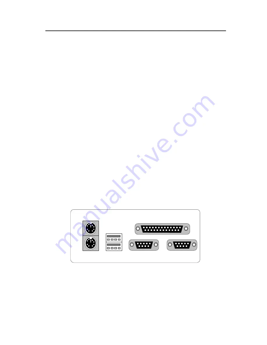
Serial 1
PS/2
Mouse
PS/2
Keyboard
Parallel Port
Serial 2
USB
USB
Step 15. Install the Display Card (ISA/PCI/AGP)
Insert the display card you have in vertical direction into the PCI/ISA expansion slot. Another
option provided for you to get higher performance for graphic-intensive applications in the system
is to insert the AGP card on the AGP (Accelerated Graphics Port) slot, which is designed intently
for exclusive use for display adapter.


