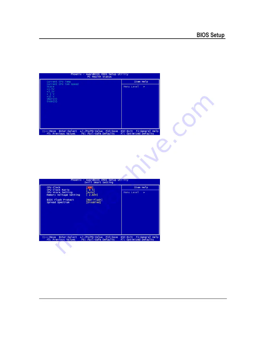
IWILL P4SP User Manual Download Page 40


Chapter 4                                                   


PC Health Status 
 

The PC Health Status screen displays system information such as CPU cooling fan speed and 
various voltage levels. This information is Auto Detected.


IWILL Smart Setting 
 

The IWILL Smart Setting screen configures CPU settings. The default settings for the CPU are 
Auto Detected. You should not change these Auto Detected settings. Configuring CPU settings 
that are different than Intel specifications can damage the Intel CPU and void the CPU warranty. 
Enable the Spread Spectrum setting to reduce interference generated by the board circuitry. 


User’s Manual                                                                                                          4 - 6


Summary of Contents for P4SP

Page 1: ...IWILL P4SP Motherboard User s Manual P4SP Version 1 0...

Page 2: ...P4SP Motherboard ii User s Manual...

Page 3: ...he equipment off and on the user is encouraged to try to correct the interference by one or more of the following measures 1 Reorient or relocate the receiving antenna 2 Move the equipment away from t...

Page 4: ...thout notice and without obligation to notify any person of such revision or change Trademarks Microsoft and Windows are registered trademarks of Microsoft Corp Intel and Pentium 4 are registered trad...

Page 5: ...5 ATX12V Power Connectors 2 6 System Memory Sockets 2 7 PCI Expansion Slots 2 7 Drive Connectors 2 8 FDD1 Floppy Disk Drive Connector 2 8 IDE1 IDE2 IDE Drive Connectors 2 8 SATA1 SATA2 Serial ATA dri...

Page 6: ...9 Connecting Front Panel Components 3 10 Completing System Configuration 3 10 4 BIOS Setup 4 1 Running the CMOS Setup Utility 4 1 Entering Setup 4 2 Standard CMOS Features 4 3 Advanced BIOS Features 4...

Page 7: ...5 Drivers and Utilities 5 1 Running the Power Installer Disc 5 1 Drivers and Utilities Installation 5 2 6 Specifications 6 1 User s Manual vii...

Page 8: ...P4SP Motherboard viii User s Manual...

Page 9: ...to integrate all system control functions Features of this motherboard include support for Intel Pentium 4 processor with support for Hyper Threading Technology 400 533 MHz system bus Up to 4GB Dual C...

Page 10: ...s how to use the bundled software drivers and utilities 6 Specifications lists the motherboard s technical specifications Package Contents The motherboard package contains the following items 1 P4SP m...

Page 11: ...omponents The motherboard provides sockets slots and connectors for the installation of the CPU memory power supply and PCI expansion cards Connectors The motherboard s connectors let you attach IDE a...

Page 12: ...P4SP Motherboard Motherboard Layout The location of motherboard components is shown below P4SP 2 2 User s Manual...

Page 13: ...ors Function SATA1 SATA2 SATA drive connectors JATXPWR2 Connectors for power supply JATXPWR1 ATX 12V power connector JPANEL1 Front panel feature connector JUSB1 JUSB2 JUSB3 Internal USB connector JCFA...

Page 14: ...S position by placing the jumper cap over pins 2 and 3 for one minute 3 Return the jumper cap to the Normal setting pins 1 and 2 4 Replace the system housing cover plug in the system and power on 5 Ru...

Page 15: ...he CPU in Chapter 3 AGP 8X 1 5V Slot The AGP slot is for the exclusive use of high speed AGP video display cards It is AGP 3 0 compliant This AGP slot supports AGP4X and AGP8X card This slot only supp...

Page 16: ...wer connectors on this motherboard can accommodate either standard For an ATX12V power supply insert the 20 pin lead of the ATX12V into the first 20 holes of the power connector leaving the last four...

Page 17: ...modules See the section on installing memory in Chapter 3 PCI Expansion Slots The PCI expansion slots let you install additional system hardware via add on cards There are five 32 bit 33MHz slots tha...

Page 18: ...sk Drive Connector The connector FDD lets you attach one floppy disk drive to the motherboard using a standard FDD ribbon cable IDE1 IDE2 IDE Drive Connectors The two IDE drive connectors are marked I...

Page 19: ...per channel For compatibility the underlying Serial ATA functionality is transparent to the operating system The Serial ATA controller can operate in both legacy and native modes In legacy mode stand...

Page 20: ...in diagram Power Switch Power On in diagram System Activity LED System LED in diagram Housing mounted Speaker Speaker in diagram JCDIN1 JAUX1 Audio Connectors These two connectors CD IN and AUX IN let...

Page 21: ...P4SP Motherboard JUSB1 JUSB2 JUSB3 Internal USB Connector These connectors JUSB1 and JUSB2 let you attach internal USB devices User s Manual 2 11...

Page 22: ...e CPU cooling fan JCFAN1 to the System cooling fans JSFAN1 These connectors all support fan speed monitoring A temperature monitor detects the CPU and internal system temperatures You can set a system...

Page 23: ...ports are for Type A USB cable connectors It does not matter if the system is on when you connect or disconnect USB devices 10 100 Mbps Ethernet Port The 10 100 Mbps Ethernet Port is an RJ 45 connect...

Page 24: ...o devices to the onboard audio subsystem The three audio jacks are 1 Line Out Green Offers output to two stereo speakers 2 Line In Blue Provides audio input connector for an external audio source 3 Mi...

Page 25: ...s carefully Installing a CPU The P4SP motherboard supports the Intel Pentium 4 processor You must install both the Intel Pentium 4 and its cooling assembly carefully and in accordance with the procedu...

Page 26: ...Carefully handle the processor by its edges and take all precautions against electrostatic discharge The boxed Intel Pentium 4 processor comes with a Heatsink and Thermal Interface Material applicato...

Page 27: ...board 2 Position the CPU above the socket such that its marked corner matches the base of the socket lever 3 Press it firmly on the socket while you push down the socket lever to secure the CPU 3 3 Us...

Page 28: ...the top of the installed CPU Fig 2 The TIM is supplied in an applicator with the boxed Pentium 4 processors The TIM secures the Fan Heatsink to the CPU However if the Fan Heatsink already has a patch...

Page 29: ...Fan Heatsink while closing the clip lever will ensure the thermal interface material TIM is not damaged and the processor will operate correctly The TIM is attached to the heatsink 6 Make sure to clos...

Page 30: ...Heatsink is symmetrical 8 With the clip levers in the up position E push down on all four clip frame corners to secure to the Retention Mechanism hooks F Close the clip levers G The levers require for...

Page 31: ...e better performance Note1 Installing two or more memory modules is recommended for this motherboard When installing two modules you must first fill the sockets A1 and B1 or A2 and B2 One Black and On...

Page 32: ...matically Note It is recommended that you install at least two memory modules beginning in sockets DIMMA1 and DIMMB1 To install memory modules 1 Unlock a DIMM socket by pressing the retaining clips ou...

Page 33: ...quired mounting hardware 2 Identify the mounting holes on the board and confirm that the housing standoffs are suitably placed 3 Install the included rear I O panel shield in the housing s I O panel o...

Page 34: ...an connect or install the internal devices you need to complete the system This will include attaching disk drives and connecting housing power supply connectors After replacing the system housing cov...

Page 35: ...battery backup when the system is powered off The values stored in the CMOS configures the system each time the system is powered on Running the CMOS Setup Utility The CMOS Setup Utility does not dep...

Page 36: ...A series of beeps if the error is encountered before the display is initialized 2 An error message is shown on the screen if the display is initialized After the POST routines are performed the follow...

Page 37: ...loppy drive settings and other settings are standard defaults that you can also change if necessary Advanced BIOS Features The Advanced BIOS Features screen configures boot options such as boot device...

Page 38: ...of these settings it is recommended that you do not change the default settings Integrated Peripherals Screen The Integrated Peripherals screen configures the peripheral features integrated onto the m...

Page 39: ...re Minimum and Maximum configurations available in addition to the User Defined defaults In User Defined mode you can customize all settings PnP PCI Configurations The PnP PCI Configurations screen co...

Page 40: ...ing The IWILL Smart Setting screen configures CPU settings The default settings for the CPU are Auto Detected You should not change these Auto Detected settings Configuring CPU settings that are diffe...

Page 41: ...start for troubleshooting of hardware problems Load Optimized Defaults Selecting Y after choosing this item loads the optimized set of default settings Use these default settings if the configuration...

Page 42: ...the password using no more than eight characters or numbers and press Enter 3 A dialog box asks you to confirm the new password by typing it in a second time Type the password again and press Enter o...

Page 43: ...e current utility configuration as a new record exits the utility and restarts the system using the saved configuration record Quit Without Saving This item lets you exit the utility and restart the s...

Page 44: ...sing the Make Driver utility This motherboard requires that you install driver software to support the onboard hardware You will need to install some or all of the following 1 Main chipset support sof...

Page 45: ...install the utility software bundled on the Power Installer CD ROM disc click on Software Utility in the Drivers and Utilities screen to open the Software Utility window To install the Adobe Acrobat r...

Page 46: ...Super I O W83627HF CPU Power Follows VRM 9 0 spec VRD design Three phase Supports Vcore output up to 78A Memory Dual Channel PC2700 PC2100 PC1600 DDR SDRAM Supports 128MB 256MB 512MB up to 1GB memory...

Page 47: ...IN One 4 pin CD ROM Audio In header One 4 pin AUX header General I O Two IDE connectors Bus Master with Enhanced to support Ultra DMA 33 ATA66 ATA100 IDE drives and ATAPI compliant devices One Floppy...

Page 48: ...core 1 5V 3 3V 5V 12V 12V Battery 5VSTB Form Factor ATX Form Factor ATX 12V power connectors Stacked PS 2 Mouse Keyboard ports Stacked 2 USB2 0 and RJ 45 LAN ports with LED Approvals FCC class B Produ...

Reviews: