background image


Page 6 of 21 

iWave Systems Confidential. 

        Telematics Control Unit Product User Manual 


Make  sure  that  Electrical  outlet  where you  connected  the  power  adapter  is  not  damaged  and  working 
fine. 


If  the  power  adapter  is  broken,  do  not  try  to  fix  it  by  yourself.  To  prevent  electrical  shock  hazard, 
disconnect the power cable from the electrical outlet before displacing the system. 


Before connecting  or removing  Telematics  Control Unit,  ensure that  power  cable is unplugged  and ESD 
antistatic guidelines. 

1.5


Unpacking Guidelines 

Please follow the below guidelines while unpacking the TCU. 

Make sure to follow the below antistatic guidelines before unpacking. 


Wear the antistatic wristband while unpacking and handling the device to prevent electrostatic discharge. 


Remove the Telematics Control Unit from antistatic cover and place it above the ESD free area. 


Use antistatic pad/mat with proper grounding to place the device. 


Don’t touch the inside surface of the Telematics Control Unit. 


Avoid using board in extreme dust, humidity and temperature conditions. 


Also, this device is not water proof, keep away from wet surface. 


Make sure that packing box is facing upwards while opening. 


Make sure that the entire packing list items mentioned in package checklist present. 

Static electricity can destroy electronics in the development platform. Make sure to follow the ESD 
precautions to prevent damage to the system and injury to us. 


1.6


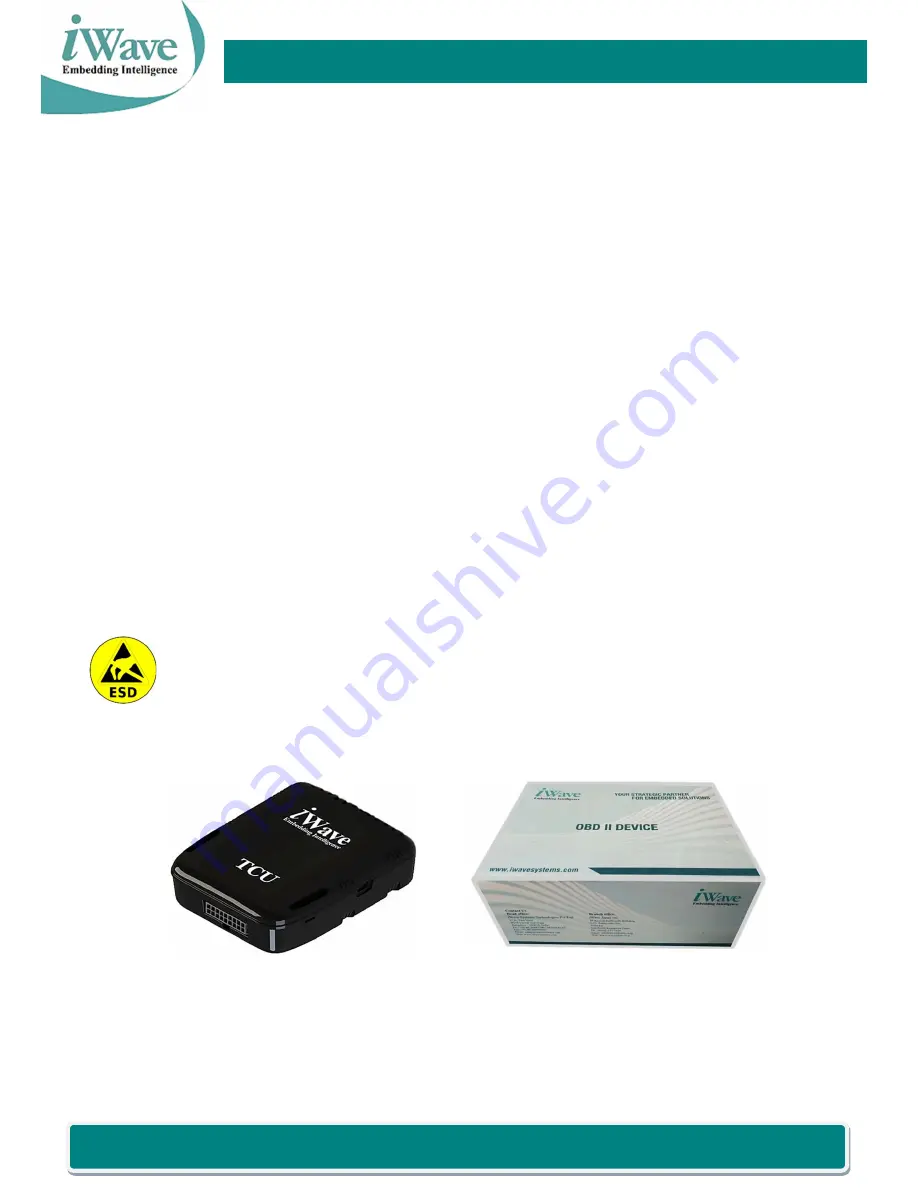
Development Kit Deliverables and Test Accessories 


Figure 1: Development Kit Deliverables 


Summary of Contents for TCU

Page 1: ...Page 1 of 21 iWave Systems Confidential Telematics Control Unit Product User Manual Telematics Control Unit Product User Manual ...

Page 2: ...of accuracy is given concerning the contents of the information contained in this publication To the extent permitted by law no liability including liability to any person by reason of negligence will be accepted by iWave Systems its subsidiaries or employees for any direct or indirect loss or damage caused by omissions from or inaccuracies in this document CPU and other major components used in t...

Page 3: ...IM INSERTION PROCEDURE 8 2 3 BATTERY CONNECTION PROCEDURE 8 2 4 BATTERY REMOVAL PROCEDURE 9 2 5 PROCEDURE TO CLOSE THE ENCLOSURE 9 2 6 POWERING THE DEVICE THROUGH Y CABLE 9 3 TELEMATICS CONTROL UNIT FLASHING AND DEBUGGING PROCEDURE 10 3 1 SETTING UP TELEMATICS CONTROL UNIT FOR DEBUG LOG CAPTURE 10 3 2 SETTING UP TELEMATICS SOLUTION FOR FLASHING 12 3 3 BINARY PROGRAMMING 12 3 3 1 LIMITATIONS 13 3 4...

Page 4: ...URE 11 TERA TERM SETTING 11 FIGURE 12 TELEMATICS CONTROL UNIT BOOT LOG 11 FIGURE 13 HARDWARE SETUP TO FLASH THE TELEMATICS CONTROL UNIT 12 FIGURE 14 PLATFORM DETECTION 12 FIGURE 15 BINARY PROGRAMMING SUCCEED 13 FIGURE 16 SERIAL COM PORT SELECTION 14 FIGURE 17 TERA TERM SERIAL PORT SETUP AND CONNECTION 14 FIGURE 18 TELEMATICS CONTROL UNIT DEBUG LOG 15 FIGURE 19 CONNECT WI FI 15 FIGURE 20 SSH LOGIN ...

Page 5: ...g Telematics Control Unit carefully read all the manuals that came with the package This Device is ESD sensitive Handle the product only in accordance with the installation instructions given in the manual Place the product on a stable surface To avoid short circuits in electronics keep all conducting material away from the Telematics Control Unit Avoid using board in extreme dust humidity and tem...

Page 6: ... the antistatic wristband while unpacking and handling the device to prevent electrostatic discharge Remove the Telematics Control Unit from antistatic cover and place it above the ESD free area Use antistatic pad mat with proper grounding to place the device Don t touch the inside surface of the Telematics Control Unit Avoid using board in extreme dust humidity and temperature conditions Also thi...

Page 7: ...oller Area Network COM Communication Port ESD Electrostatic Discharge FTP File Transfer Protocol HID High IntensityDischarge IP Internet Protocol OBD On Board Diagnostics OTG On The Go RoHS Restriction of Hazardous Substances SIM Subscriber Identification Module SSH Secure Shell SSID Service Set Identifier TCU Telematics Control Unit TELNET TELecommunications NETwork USB Universal Serial Bus Table...

Page 8: ...ure 2 2 SIM Insertion Procedure Unlock the SIM Connector and insert the Micro SIM Card in the SIM connector which is present on the top side of the board as shown in image 1 and image 2 of Figure 4 Lock the SIM Connector as shown in image 3 of Figure 4 Figure 4 SIM insertion procedure in Telematics control unit 2 3 Battery Connection Procedure Connect the battery in the slot highlighted as in imag...

Page 9: ...hown in the image 1 of Figure 7 Close the enclosure Figure 7 Procedure to close the enclosure 2 6 Powering the device through Y Cable Place the board and Connect the Y cable as shown in image 1 and image 2 of Figure 8 Connect one end of the Y cable to the Power connector board as shown in the image 3 of Figure 8 Provide power supply to the power connector board as shown in the image 4 of Figure 8 ...

Page 10: ...9 Connect the one end of the USB Cable to the Serial Debug Board as shown in image 2 of Figure 9 Power on the Telematics control unit as described in Figure 9 Connect the other end of the USB cable to PC to view the Debug prints Figure 9 Procedure to connect Serial Debug Device Install the Tera Term tool in the Windows Host PC Open the Tera Term Tool available on the host PC and select the appropr...

Page 11: ...ra Term settings as mentioned below Figure 11 Tera Term setting Make sure the Tera Term has below settings and click on OK button Bits per second 115200 bps Data bits 8 Parity none Stop bits 1 Flow control none Power ON the Telematics control unit and the Debug log will appear as shown in Figure 12 Figure 12 Telematics control unit Boot log ...

Page 12: ...ontrol unit is powered on before connecting the USB flashing cable Remove the USB flashing cable before powering off the device after flashing 3 3 Binary Programming Use USB type A to micro B cable to connect the Telematics control unit with host PC via USB OTG port Extract the MFG_Tool zip file from MFG_TOOL folder Navigate to MFG_TOOL MFG_Tool folder and double click on MfgTool2 exe file The MFG...

Page 13: ... or click the Cancel button It will not affect any function If you stop the application in between of programming binaries and if you re start the application will try to continue from the point where you stopped before But it is not guaranteed that it can continue successfully It is NOT recommended to do this Login Credentials of OBD2 Device User name root Password iWavesys123 3 4 Login to the De...

Page 14: ... port and change the Tera Term settings as mentioned in Figure 17 Figure 17 Tera Term Serial port setup and Connection Make sure the Tera Term has below settings and click on OK button Bits per second 115200 bps Data bits 8 Parity none Stop bits 1 Flow control none Power ON the Telematics control unit and the Debug log will appear as shown in Figure 18 ...

Page 15: ...vice Wi Fi will come up Turn on Wi Fi in any Laptop and connect to OBD device Wi Fi SSID OBDDevice003 Password iWavesys123 IP Address 172 24 1 1 Using SSH connect to the board with the below login details Username of OBD2 Device root Password of OBD2 Device iWavesys123 3 5 1 Login to device console from Windows PC Turn on Wi Fi in laptop Power on the device and wait for 1 min OBDDevice003 Wi Fi wi...

Page 16: ...l like Tera Term putty etc Here Tera Term is used to login to the device Connect to the device with host IP address as shown in the figure Select service SSH Host address 172 24 1 1 Click OK Figure 20 SSH Login Enter the Telematics control unit user name and password as shown in the Figure 21 User Name root Password iWavesys123 Click OK Figure 21 SSH Login Details ...

Page 17: ... Figure 22 Device Console Window 3 5 2 Login to device console from Android Phone Install any SSH terminal application from the Play store Eg SSH SFTP FTP TELNET Advanced Client Admin Hands Turn on Wi Fi in the phone Power on the device and wait for 1 min OBDDevice003 Wi Fi will come up as shown in the figure Figure 23 OBDDevice003 Wi Fi connection ...

Page 18: ...ystems Confidential Telematics Control Unit Product User Manual Open the SSH terminal application in phone Figure 24 SSH Terminal Application in phone Click on the Plus symbol as shown in the figure Figure 25 SSH Connection ...

Page 19: ...fidential Telematics Control Unit Product User Manual Enter the login details and click on the save button as shown in the figure Figure 26 SSH Login Details Click on the saved host name as shown in the Figure 26 Figure 27 SSH Login ...

Page 20: ...21 iWave Systems Confidential Telematics Control Unit Product User Manual Select SSH Terminal from the list Figure 28 SSH Login The debug console will open as shown in the Figure 29 Figure 29 Device Console Window ...

Page 21: ...ed to provide the best possible support for our customers so that our Hardware and Software can be easily migrated and used For assistance contact our Technical Support team at Email support obd iwavesystems com Website www iwavesystems com Address iWave Systems Technologies Pvt Ltd 7 B 29th Main BTM Layout 2nd Stage Bangalore Karnataka India 560076 ...

Reviews: