installation directiVe
6
N40 ENT M25
N60 ENT M37-M40
MAY 2006
Figure
05_042_C
pin 1
pin
05_043_C
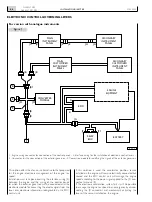
The JB connector will be coupled to the JB connector of the
engine wiring, while the JB1 connector will be coupled to the
JB connector of the wiring connecting the control panel.
The converter module will be connected to the JO
connector while the JD connector will be available to make
the connections to the electronic governance system unit.
Figure 2
1. Connector JB1 - 2. Connector JD - 3. Connector JO - 4. Connector JB.
1
2
3
4
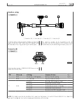
Interface wiring
Connector JD
note:
The voltage values for the rotation of the motor must be between 0.2 and 4.8 V. Values below 0.2 V or above 4.8 V
generate the recognition of a fault and consequent deactivation of the function.
pin
Wire code
(u) Voltage
interpreted function
i
max
1
7731
+B with key in ON position
Electronic throttle enabling
0,5 A
2
0000
0 V - (Ground)
Common reference terminal
-
3
5584
0 to 0,2 V
Poor value. EDC recognises a fault
-
0,2 to 0,5 V
Accelerator at minimum level
0,5 to 4,5 V
Accelerator min. to max., U function
-
4,5 to 4,8 V
Accelerator at maximum level
-
4,8 to 5 V
Excessive value. EDC recognises a fault
The connection requires a METRI-PACK 150 three-way con-
nector with male terminals.
Summary of Contents for NEF N40-ENT-M25
Page 64: ...INSTALLATIONDIRECTIVE 64 N40 ENT M25 N60 ENT M37 M40 MAY 2006 ...
Page 69: ......


