background image

ORBIMAT CA

  |  Operating instructions 


Service and troubleshooting

(09.03.15) OW_ORBIMAT_CA_BA_871060202_04_EN 

 orbitalum tools

 GmbH, D-78224 Singen, www.orbitalum.com, Tel. +49 (0) 77 31 792-0

        71

15

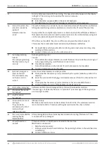
Short-circuit  
(current flowing, but 
no voltage)

The electrode has contacted the workpiece during the process.
This leads to a reduction of the arc voltage below the "standard" value (from approx. 
10 V); the system detects a short-circuit regardless of the settings in the monitoring 
limits.


X

Eliminate short-circuit.


X

Re-grind electrode.


X

Grind out any tungsten inclusions in the weld seam.

16

Forming gas pressure

When used with forming gas pressure regulation.
The actual value of the pressure deviates too strongly from the specified setpoint value 
(warning or process abortion).
Causes:
•  Actual value too low; see interior pressure reading in display.
•  Possible excessively low input pressure from bottle manometer.


X

Ensure that there are no excessively large gaps (pipe joint?).


X

Ensure that the plugs are sealing tightly so that pressure can build up.


X

Set the pressure regulator on the BUP box to max. 10 bar if applicable.


X

Correct input pressure from bottle manometer if applicable.

See also: Operating instructions of the BUP unit itself.

17

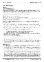
Error code

Internal read-write error in the software.
"Error code" is followed by the error in "plain text" (see messages 18 through 28) or a 
two-digit number.


X

Contact Orbitalum service.

18

General errors

Plain-text message which can appear with the "Error code" message (message 17).


X

Contact Orbitalum if the problem cannot be resolved.

19

Parameter error

20

Incorrect file name

21

Drive not found

22

File not found

23

Path not found

24

Folder full

25

Drive full

26

Drive not ready

27

Write protection

28

File access error

29

Additional procedures 
cannot be created!

For messages with "90%" specifications:
Resources almost used up. Additional data can still be saved.

Recommendation:


X

Clean up system by deleting or externally saving data which is no longer required.

The number of folders and procedures per folder is limited to 100, however.

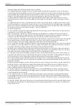
30

Over 90% of resources 
used up for procedures!

31

Additional folders can-
not be created!

32

Over 90% of resources 
used up for folders!

33

The procedure cannot 
be loaded!

Procedure cannot be loaded after switch-on.
When the machine is switched on, the last used program is loaded. If this is not possible 
(e.g. memory card removed), the default program is loaded.


X

Contact Orbitalum if the problem cannot be resolved.

34

A problem occurred when saving the procedure.
The error appears in "plain text" (see messages 18 through 28) or as a two-digit number.

Summary of Contents for Orbitalum ORBIMAT 165 CA

Page 1: ...g Power Supplies ORBIMAT 165 CA ORBIMAT 300 CA Machine no To work safely with this machine please read through the operating instructions in full before initial operation Retain the operating instructions for future reference Code 871 060 202 EN Translation of original operating instructions ...

Page 2: ...ed in particular the rights of duplication and distribution as well as translation Duplication and reproduction in any form print photo copy microfilm or electronic require the written permission of Orbitalum Tools GmbH ...

Page 3: ...coolant 24 7 3 6 Closing off gas hose 24 7 4 Initial operation 25 7 4 1 Adding coolant 25 7 4 2 Commissioning the power source 26 8 Operation 29 8 1 Auto programming 29 8 1 1 Setting parameters 29 8 1 2 Configuring weld head 29 8 1 3 Configuring material 30 8 1 4 Configuring protective gas 30 8 1 5 Configuring pipe diameter 31 8 1 6 Configuring wall thickness 31 8 1 7 Configuring wire feed 31 8 1 ...

Page 4: ...er mains voltages OM 165 CA only 62 9 Service and troubleshooting 63 9 1 Performing service work 63 9 1 1 Pumping out coolant 63 9 1 2 Performing motor calibration 63 9 1 3 Adjusting an external printer 64 9 1 4 Switching on an internal printer 65 9 1 5 Printing a test page 66 9 1 6 Service Screen 66 9 1 7 Info 66 9 2 Possible application operating errors 67 9 2 1 Uneven weld seam current fluctuat...

Page 5: ...is safety symbol in order to avoid injuries or death Warning symbol Meaning DANGER Direct danger Non observance could result in death or critical injury Restrictions if applicable X X Measures to prevent danger WARNING Possible danger Non observance could result in serious injury Restrictions if applicable X X Measures to prevent danger ATTENTION Dangerous situation X X Non observance could result...

Page 6: ...ns Abbr Meaning OM CA ORBIMAT CAdvanced 1 4 Warning symbols Observe all of the warnings and safety instructions affixed to the machines The following labels also appear on the machine Image Machine model Position on machine Meaning Code ORBIMAT 165 CA ORBIMAT 300 CA Rear DANGER Danger of injury from electric shock ORBIMAT 165 CA ORBIMAT 300 CA Rear DANGER Danger of injury from electric shock ...

Page 7: ...ot contaminated Proper use also includes the following observing all safety instructions and warning messages included in these operating instructions carrying out all inspection and maintenance work sole use in the original condition with original accessories spare parts and materials processing only materials set out in the operating instructions 2 2 2 Improper use A use other than that defined ...

Page 8: ...act a disposal center near you for this purpose Important for Germany our products may not be disposed of in municipal disposal sites as they are only used for industrial purposes as per RL 2002 96 EC 2 4 Basic safety instructions The machine hereinafter referred to as the ORBIMAT 165 CA or ORBIMAT 300 CA is a state of the art machine designed for safe use The risks involved in using the machine a...

Page 9: ...nance of the system Various injuries and damage to property X X Carry out maintenance as described in the Maintenance chapter see chap 10 p 78 DANGER Electrical hazards through touching and incorrect or damp safety equipment Electric shock Do not touch energized parts pipe especially when igniting the arc Do not allow persons with increased sensitivity to electrical hazards e g weakness of the hea...

Page 10: ...onents can cause physical injury Do not misuse the cable e g such as using it to suspend or carry the machine X X Replace defective safety components immediately and check them daily to ensure proper operation X X Have an expert replace defective power cables immediately X X Clean and perform maintenance on the machine after each use X X Keep cables away from heat oil sharp edges and moving equipm...

Page 11: ... and substances during the welding process and handling of the electrodes Health problems including cancer X X Use extraction devices as per the professional association regulations e g BGI 7006 1 X X Extra caution is required with chrome nickel and manganese Do not use electrodes containing thorium ATTENTION Hot surfaces of the weld head and weld points including for a period of time after weldin...

Page 12: ...reader 6 Flowmeter 7 Front panel 8 Main switch 9 Hood 10 Softkeys 11 Display 10 5 For a detailed description of the different operating elements buttons switches and connectors see chap 7 1 p 20 3 2 ORBIMAT 300 CA 11 1 10 9 8 2 3 4 5 6 7 1 Display housing 2 Printer cover 3 Integrated printer 4 Rotary knob 5 Multicard reader 6 Flowmeter 7 Front panel 8 Main switch 9 Hood 10 Softkeys 11 Display 10 5...

Page 13: ...mperature Including water flow sensor Significantly increases cooling performance for the weld heads Particularly suitable for welding units in series production Suitable for all ORBIMAT orbital welding power supplies For ORBIMAT 165 CA CB The ORBIMAT 165 CA has to be modified in our plant 889 000 001 For ORBIMAT 300 CA CB 889 000 002 ORBITWIN switching device To increase productivity the switchin...

Page 14: ... of the seam weld into the sump position At the same time the gas pressure is modified automatically during welding by the system between a programmable minimum and maximum value depending on the position of the electrodes Including ORBIPURGE forming set for tube ID 12 110 mm 0 472 4 331 For ORBIMAT 165 CA 300 CA 886 000 001 Coolant OCL 15 Pre Mix for ORBIMAT power sources and cool ing systems to ...

Page 15: ...lash card 32 MB for transfer ring data between the machine and PC 1 USB card reader for exporting the CompactFlash card on the PC no further device required ORBIPROG_CA software allows programs and protocols to be stored on the PC 875 050 003 Paper rolls For the integrated ORBIMAT printer Suitable for all ORBIMAT orbital welding power supplies Contains 3 paper rolls 875 050 017 Ribbon cartridges F...

Page 16: ...ver 5 000 welding programs providing systematic and clear program management thanks to the creation of folder structures Welding data logging and printout of actual values A multicard reader enables data to be transferred easily to an external PC It is possible to extend memory and data exchange using CompactFlash card CF SD MMC Sony memory stick Optional PC offline software with the capability to...

Page 17: ... ignition 4 3 Functional description The machine is supplied with voltage and controlled by the orbital welding power supply The weld head is clamped to the pipe to be welded using clamping inserts or clamping jaws The weld head is ar ranged in such a way that the weld electrode is located radially over the weld joint After ignition of the weld arc the electrode is guided around the workpiece at t...

Page 18: ...eproducibility 0 5 0 5 Rated current at 100 ED A DC 120 220 Rated current at 60 ED A DC 260 Rated current at 40 ED A DC 300 Rated current at 30 ED A DC 165 Weld voltage min V DC 10 10 Weld voltage max V DC 16 22 Open circuit voltage max V DC 85 86 Cable diameter min mm2 16 35 Ignition power max Joule 0 9 0 9 Ignition voltage max kV 8 8 Output control Rotation motor voltage max V DC 24 24 PWM signa...

Page 19: ...iately 6 2 Included with the machine Subject to modifications 1 Orbital welding power source of the ORBIMAT CA series 1 Hose connection set ORBIMAT Code 875 030 018 1 Dummy plug for insertion into the connection of the remote control if no external remote control will be used Code 875 050 006 1 Bottle with 2 litre 67 6 fl oz of coolant OCL 15 Code 875 030 015 only with 165 CA 1 Filling funnel Code...

Page 20: ...using the rotary knob Item 6 and confirmed by pressing the rotary knob Detailed descriptions are provided with the explanation of the respective operating steps 1 6 2 3 4 5 1 Push switch softkey 1 2 Push switch softkey 2 3 Push switch softkey 3 4 Push switch softkey 4 5 Push switch softkey 5 6 Rotary knob Fig 1 Main control elements 7 1 2 Connections and control elements on the front panel 7 2 6 5...

Page 21: ... disabled key position the key can be removed Connection oxygen meter Connection of a residual oxygen meter optional For continuous monitoring of the forming gas The portion of residual oxygen remains below a percental portion which can be set at the device e g 70 ppm Connection of BUP Control Box For supplementary devices for control of the forming gas pressure BUP BackUp Pressure Control optiona...

Page 22: ...ting menu and navigating to the next higher menu level X X Press the rotary knob for more than 2 seconds The menu of the next higher level appears in the display Setting a parameter Entering a value X X Highlight a field The field appears in red X X Change value within the specified limit values Turn rotary knob X X Save value and exit field Briefly press the rotary knob 7 2 2 Operation via push s...

Page 23: ...e and weld head so that they are stable 7 3 1 Setting up machine X X First set up system for connection in such a way that it is as accessible as possible from the front and back X X Ensure that the machine is disconnected from the mains network on all sides X X Secure machine against being switched on accidentally 7 3 2 Connecting a gas bottle 1 Check stability of the gas bottle Secure gas bottle...

Page 24: ...ction Fig 3 Item 1 A dummy plug Fig 4 Item 5 must be inserted into the remote control connection if remote control will not be used standard scope of delivery The system may only be operated if either the dummy plug is inserted or a remote control is connected 6 Insert a dummy plug into the remote control connection Fig 4 Item 5 if necessary Properly connected weld head Fig 4 Weld head connected 7...

Page 25: ...X X With closed weld heads ensure proper working order of the eye protection WARNING Hot leaking liquids and hot plug connections during heavy operation Danger of scalding X X Heed the safety precautions of the technical supervisor person in charge of safety ATTENTION Hot surfaces of the weld head and weld points including for a period of time after welding Danger of burns X X Wear safety gloves 7...

Page 26: ...ilot light in the main switch is lit up Is the pilot light not lit up There is a problem with the power supply no voltage plug not inserted X X Check whether the power plug is properly inserted X X Have the power supply checked Is the pilot light lit up X X Check whether the STOP indicator for active EMERGENCY STOP on the front panel is lit up Is the STOP indicator on the front panel lit up With e...

Page 27: ...pears Fig 6 Sub menu System Adjustments 5 Select the Pump water out menu item 6 Briefly press rotary knob The Pumping water out message appears The Cancel button is highlighted in blue Fig 7 Sub menu Service Fig 8 Pumping out water 7 Allow water pump to run until the coolant exits the drain hose under pressure 8 Confirm Cancel by briefly pressing the rotary knob The water pump is switched off The ...

Page 28: ...49 0 77 31 792 0 09 03 15 OW_ORBIMAT_CA_BA_871060202_04_EN If the coolant does not exit the hose within a maximum of 10 seconds 1 Cancel drainage as prolonged dry running can damage the pump 2 Check coolant level 3 Check whether the pump is running and if a pumping sound can be heard Additional help see chap 9 p 63 ...

Page 29: ...menu item The following display appears Field Return to main menu Fields Weld head model to Wall thickness Parameter entry Field Wire feed Welding with without filler wire Calculate procedure Calculation of the procedure with the entered parameters Fig 9 Sub menu Auto programming 8 1 2 Configuring weld head 1 Select Weld head field and briefly press the rotary knob The following display appears A ...

Page 30: ...eld and briefly press the rotary knob The following display appears Materials in the list Chrome nickel steels Five materials Ferritic materials Two materials Titanium Ti Fig 11 Selecting material Does the material used not appear in the list X X Select the most similar material example for stainless steels one of the chrome nickel steels 1 Select material 2 Confirm by briefly pressing the rotary ...

Page 31: ...hich might require carrying out your own weld tests Auto programming can be helpful here because you can enter the thickness of the bluntly joined root face usually 1 5 2 5 mm 0 059 0 098 as the wall thickness first and then manually improve the auto programmed procedure calculated in this way 2 Select value by pressing the rotary knob 3 Enter values via the external keyboard or the rotary knob 8 ...

Page 32: ... of 2 4 mm 0 094 electrodes can lead to a worsening of the ignition characteristics and wandering of the arc at the electrode X X Ensure a good grinding of the electrode Use an appropriate electrode grinding device such as the ESG Plus tungsten grinder recommendation WARNING Sharply ground and pointy electrodes Danger of injury X X Store ground electrodes so that there is no danger of injury 8 2 3...

Page 33: ...ftkeys for controlling the motor changes X X Press Motor forward or Motor backward button The motor runs in the selected direction as long as a button is being X X Press softkey 2 Home The weld head turns to the open position X X Press softkey Motor OK to exit the operating diagram X X Press softkey 5 Menu to change directly to the main menu 8 2 4 Connecting forming gas With orbital welding suffic...

Page 34: ...ource programmed D D Weld heads prepared for welding Properly connected and positioned D D Gas bottle secured and opened D D Machine switched on D D The main menu appears in the display X X Press softkey 1 Weld The machine is ready to start The Start button in the display is red X X Press softkey 1 Start or X X Press START button on an external remote control if connected or X X Press red START ST...

Page 35: ...ol In the individual sectors the respective current sector is highlighted in white and the accompanying red indicator indicates the current electrode position The current sector number and cur rent position in angular degrees appear in the bottom section of the graphic Info field The following information appears in the info field below the graphic Name of the folder in which the proce dure is sav...

Page 36: ...e and this can be compensated for by over welding it Premature slope off of a running process X X Press softkey 2 Final slope or X X Press the Final button on the weld head or X X Press slope off symbol on connected remote control The machine slopes off the weld current as per the procedure The weld head continues running during the slope off phase After slope off the weld current is switched off ...

Page 37: ...in the Limit for correction factor field in which the operator can change the correc tion factor in completed mode production mode Example Specification 5 Change in range from 5 to 5 absolute range 10 2 Adjust and save value with rotary knob or keyboard Fig 16 Limit for correction factor 8 3 3 Adjusting individual parameters Individual parameters are adjusted in the respective sectors 1 Select sof...

Page 38: ...ameters 2 Select highlight adjust and save parameters X X Press softkey 1 Weld or softkey 2 Test The machine is ready to start Fig 17 Input field Gas post purge time 8 3 5 Adjusting ignition current end current and current slope off X X Adjust values specified by auto programming only in exceptional cases e g with extremely thin walled pipes Ignition current Value specified during ignition The ign...

Page 39: ...he 1st sector affects the energy introduced to the melt pool during pool formation X X Ensure that the weld current of the 1st sector is used during pool formation 1 Using the go further to gas pre purge time go further to start delay time buttons select adjust and save parameters or 1 In the main menu select Manual Adjust programming Adjust parameters 2 Select highlight adjust and save parameters...

Page 40: ...h currents in the same direction to obtain the desired pulse effect 1 In the main menu select Manual Adjust programming Adjust parameters 2 Select desired sector The respective selected sector is highlighted in color to the right in the display The angular degree of this sector is specified 3 Select highlight adjust and save the HP current LP current and Slope parameters 4 Press softkey 1 Weld or ...

Page 41: ...ing weld speed and transition time Slope Auto programming specifies weld speeds in the range of 70 100 mm min at pipe circumference which lie in the me dium range for the TIG process As of a certain wall thickness the system drives the motor in sync with the pulse The motor remains nearly still during the high pulse phase and moves only during the low pulse phase This method reduces the volume of ...

Page 42: ...LP Speed in mm min Changing the wire feed quantity requires a change to the current since more cold material is introduced to the weld ing process with an increased wire speed for example If the wire quantity is too high it is difficult to control the melt pool in the individual positions or it breaks away or drips off Wire start delay The time from ignition of the arc to the introduction of wire ...

Page 43: ...select the desired sector The respective selected sector is highlighted in color to the right in the display The angular degree of this sector is specified An image of the seam scale appears below the process graphic 4 Select highlight adjust and save the Wire HP Speed and Wire LP Speed parameters 5 Press soft 1 Weld or softkey 2 Test The machine is ready to start 8 3 10 Changing the sector Auto p...

Page 44: ...ight 2 Move pointer to the 45 position with the rotary knob 3 Briefly press the rotary knob The new sector border is set and the sector list is updated The new sector appears in the list The parameters of the new sector are copied from the previous sector 4 Adjust parameters of the new sector Example Delete sector 1 1 In the main menu select Manual Adjust programming Devide into levels The sector ...

Page 45: ...o option for Create new folders The folder structure is deactivated All procedures are saved in the main directory Saving a procedure under existing name The name of the folder in which the procedure is saved appears in the Folder field in the display 1 Press softkey 3 Save A prompt appears 2 Confirm the prompt with Yes 3 The procedure is saved with the adjustments Saving an adjusted procedure und...

Page 46: ...re is saved The main menu appears If unsaved procedures are saved or adjustments were rejected 4 Call up procedure again The selected program appears in the display 8 5 Locking machine with key switch The machine features two views of the main menu Long form Procedure programming mode Procedures can be changed and sensors and monitoring functions can be activated deac tivated Short form Production...

Page 47: ...ercental value or If no adjustment is desired Enter value 0 4 Save procedure 5 Lock machine with key switch 8 6 Tacking function 1 Select test mode or weld mode with softkeys 1 or 2 2 Select pool formation with go backward or go forward 3 Select the Yes option for Tacking The following four fields are activated 4 Accept or adjust suggested parameters 5 Test tacking function Carry out welding on a ...

Page 48: ...purge times of 30 seconds if a closed weld head is selected The machine can first fill the weld head with a higher gas pressure during the gas pre purge time to reduce the time The gas pre purge time is the total time for filling the welding pocket before welding Only values which are at least 2 seconds shorter than the total gas pre purge time are possible for the flow force This time difference ...

Page 49: ...n to the machine The machine cannot be started as long as the residual oxygen value lies above the set limit value If the limit value is exceeded the process is canceled and a note is entered in the log 8 8 2 Connecting and configuring the BUP control unit The BUP control unit enables a defined and programmable internal pipe pressure forming gas to be built up in con junction with suitable plugs f...

Page 50: ...d wire required For LP heads The optional ground wire can also be used in conjunction with the manual welding torch Procedures can be adjusted and saved for manual operation Functions in manual operation Torch button on manual torch The torch button functions in four cycle operation Start process by pressing the button During the welding process press the torch button again and hold it down The ma...

Page 51: ...st of weld head models appears in the display The connected manual torch is detected automatically 3 If the manual torch is not detected Select weld head model from the list and save it 4 Press softkey 1 Weld The machine is ready to start Fig 25 Manual torch selection 8 8 4 External remote control Connecting a remote control 1 Removing the dummy plug in remote control connection of the machine 2 C...

Page 52: ... the values for the warning message a warning message is output but the running process is not interrupted In case of overshooting or undershooting the values for procedure abortion the running process is interrupted During the process the following parameters are displayed for informational purposes Mains voltage Water temperature 8 9 2 Adjusting limit values X X In the main menu select System se...

Page 53: ...The process continues running The operator can carry out other measures Maximum HP current abort Upward deviation of the high pulse current HP If the specified deviation 10 A is reached welding is aborted Example 60 A is programmed for the high pulse current in a sector During the process a value of 70 A 10 A is mea sured The process is aborted The gas post purge time is still complied with This m...

Page 54: ...bol Data is being deleted from the internal memory 2 Press button for desired deletion process 3 Confirm message Data procedure log etc is deleted Fig 28 Deleting procedures Deleting data on the external memory card 1 In the main menu select System settings Program settings 2 Select External memory in the Memory location field 3 Select deletion in the main menu via the Delete procedure button Red ...

Page 55: ... comments e g a description of the seam preparation an angle setting of the electrode with adapter about a procedure can be entered for the operator This information may be required for ensuring consistent results while running the procedure Entering notes and comments 1 In the main menu select System settings Program settings Process details A list for entering process relevant non electrical par...

Page 56: ... diskette symbol 1 Remove memory card from the slot 2 Disengage card reader using the ejector remove it from the housing and insert it again 3 Insert memory card into the slot again Using external memory card Use depends on the software version Machines supplied before May 2008 software version lower than 0 2 00 The external memory card must be activated 1 In the main menu select System settings P...

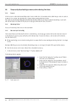
Page 57: ...ck The logs can also be brought up in the display of the machine X X Display data of the logs actual current values weld speed and arc voltage as a table in the display 8 10 4 Viewing and printing data Configuring printer D D External printer connected if applicable X X Select the desired printer in the main menu System settings Printer selection Select internal for internal printer In addition se...

Page 58: ...d at the end of the current welding process which is comprised of the current date and time Example see Fig Log file with the number 20080306 165852 3 6 08 at 4 58 52 p m The logs are identified by color Green with check All measured actual values lie within the monitoring limits for alarm and abort Yellow with exclamation mark An alarm message is output while welding The alarm limit values specif...

Page 59: ...anguage files The software components can be updated saved and restored individually and independently of one another To edit several software components the steps must be carried out individually for each software component When executing the described functions for updating and saving the software write read and copy processes are carried out between the internal memory and an external card X X ...

Page 60: ...m files Restore 2 Select software component 3 Follow the instructions on the display 8 15 Working in other languages Currently the following languages are available in the standard scope of delivery of each CA power source German English Spanish French Italian Polish Hungarian Danish Turkish Russian Chinese Japanese and Korean 8 15 1 Changing the languag 1 In the main menu select System settings L...

Page 61: ...he collaboration of Orbitalum 8 16 Importing programs from other Orbitalum power sources This function is implemented starting with software version 0 1 05 2 28 07 Thus procedures can be imported from Orbitalum devices which are either no longer being produced or which work with a different operating system A procedure import to any CA machine is possible from the following units ORBIMAT 160 C 250...

Page 62: ...are related problems are occurring also possible via simultaneous pressing of softkeys 1 5 ERR Printing deletion of system error messages SLO Switches the slope representation from standard to seconds 8 18 Operation of the system with other mains voltages OM 165 CA only The OM 165 CA machine features a wide range input for the mains voltage input voltage The machine can be set in the voltage range...

Page 63: ...e blue without the water sensor in the return being able to interrupt the process To protect the pump against dry running this process is limited in time to approx 30 seconds 4 Select Abort when the coolant is fully pumped out to avoid unnecessary dry running of the pump If the tank is not pumped empty X X Start process again Additional information can be found in Commissioning power source see ch...

Page 64: ...the deviation is less than 1 Confirm message with No 3 If the deviation is greater Confirm message with Yes and save value The machine is aware of the fault of the current connected weld head and compensates for it in the process Fig 34 Motor calibration WARNING If a display appears see Fig 35 the weld head can be calibrated 1 Ensure that the head can rotate freely electrode and that there is no d...

Page 65: ...nting the axis so that the axis audibly engages Attach paper roll in such a way that the paper rolls off toward the back Attach axis as shown on the sticker in the paper compartment 5 Cut off paper start straight and insert it into the printer 6 Move paper forward by pressing the line advance button Paper is not to be pulled through by hand 7 Guide paper through the slot in the cover and close cov...

Page 66: ...log Out Current values of the analog outputs of the computer Inverter Status of the serial interface used for communication between computer and power source RS232 Actual Val Display of the current actual value of the running process calculated from the information of the analog inputs or serial inverter interface 1 Press Service Screen button The following display appears 2 Press Service Screen b...

Page 67: ...at the start of the seam Gas pre purge time may be too short Annealing colors gradually fade as welding progresses Annealing colors at the end of welding Gas post purge too short or closed weld head possibly opened too early Depending on the design more annealing colors occur on the outside of the pipes with open weld heads TP series than with cassette heads TP weld heads invariably react with mor...

Page 68: ... the pocket which can lead to an extremely irregular arc The same applies if too much forming gas is used and it comes out at the weld joint at relatively high pressure X X Regulate gas quantity Excessively high forming gas pressure Heavy outward swelling of the seam with a type of hollow groove inside the pipe Hole formation also often oc curs at the end of welding if the excessive pressure of th...

Page 69: ...mation during the process The message can be combined with the parameters of voltage current or speed and the high or low specification The message shows that the limit value specified in the monitoring limits for the alarm were overshot or undershot for the corresponding parameter Example Warning Low speed The limit value of the weld speed specified for the alarm was reached during the low curren...

Page 70: ...sive arc voltage High transition resistances in weld circuit plug ground contact etc For cassette heads Worn current water cables 10 Speed Supplement to Warning The limit values specified in the monitoring limits warning of the speed were overshot or undershot X X Check limit values X X Check weld head speed X X Carry out motor calibration if ne 11 Speed abort The weld speed has overshot or unders...

Page 71: ...s of the BUP unit itself 17 Error code Internal read write error in the software Error code is followed by the error in plain text see messages 18 through 28 or a two digit number X X Contact Orbitalum service 18 General errors Plain text message which can appear with the Error code message message 17 X X Contact Orbitalum if the problem cannot be resolved 19 Parameter error 20 Incorrect file name...

Page 72: ...ness lie outside the value range of auto programming e g wall thicknesses over 4 mm X X Use other parameters Data of the database on the internal CF card not present or not readable X X Contact Orbitalum to restore the data 38 External storage me dium not found The card reader may not have a card in serted Access to external memory card not possible X X Check whether the memory card is detected by...

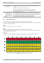
Page 73: ... Internal control voltages for PC motor valves etc are active For OM 165 CA and OM 300 CA units Indicator B2 printer power supply unit Indicator lights up if the internal printer was switched on by a print command Yellow LEDs Indicate various functions Switched on or off depending on the operating condition of the system and the function 1 2 3 4 5 6 7 8 A Fuse 1 Weld head defective Fuse 2 Printer ...

Page 74: ...wer supply unit The power supply unit provides operating voltage to the rotation motor and if ap plicable the motor of the cold wire supply unit B4 No function lights up internally bridged to B3 B5 PC controller power supply unit The power supply provides voltage to the control computer In case of a failure the system will not start i e the display will remain dark B6 Internal voltage Control volt...

Page 75: ...is pressed If the machine does not respond to this command you can check whether the signal is arriving or the button on the weld head is defective The check only makes sense if the voltage supply for the weld head is functioning see LED B1 D6 Motor button LED lights up when the button on the weld head is pressed If the machine does not respond to this command you can check whether the signal is a...

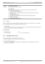
Page 76: ...ing If an external device with the abort function is connected e g residual oxygen meter the function must be activated so that the abort signal is processed by the unit in the machine If an external device is not connected the function must be deactivated X X When deactivating sensors and monitoring limits be aware that the corresponding monitoring function is no longer active Example With the ga...

Page 77: ...78224 Singen www orbitalum com Tel 49 0 77 31 792 0 77 9 6 Setting date and time 1 In the main menu select System settings System adjustments The following display appears 2 Highlight activate and enter values for the Year Month Day Hour Minute and Second fields one after another 3 Press softkey 3 Save Fig 38 System adjustments ...

Page 78: ...ake sure that the weld head is completely filled with coolant al low the weld head to run for approx 3 mins key GAS water 2 Check coolant level and refill if necessary X X If anti freeze is used Supplement with water appropriately X X Wipe off display with a slightly damp cloth Do not use cleaning agents Monthly X X Clean machine fully from the outside X X Check power cable power plug and machine ...

Page 79: ...lean machine 8 Screw side panels back on 9 Close hood again and screw it tight 10 1 2 Storage X X If the machine will go unused for a longer period of time dismantle the machine and store it in a suitable place X X Recommendation Carry out the following activities before storage 1 Clean machine 2 Remove cooling agent For this purpose loosen cooling water return of the weld head on the back of the ...

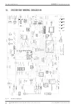
Page 80: ... 119 cable 82 cable 83 cable 118 cable 83 cable 130 cable 64 cable 140 115 cable 81 cable 82 cable 60 cable 23 cable 125 cable 126 cable 112 cable 123 cable 103 cable 7A 40 41 24 VDC Arc Starter ON OFF X 106A 24 VDC 1 4 1 2 4 1 4 1 2 3 red dark blue 2 1 1 2 1 2 1 2 1 4 1 6 1 4 black black black black black blue blue orange blue blue blue white 2 3 orange yellow 1 6 1 2 6 RED 5VDC 1 4 red grey 1 2 ...

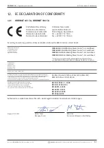
Page 81: ...IN BUP Control ORB 1001 ORBmax ORBICOOL OT DVR etc Seriennummer Series number Numero di serie Nombre de série Número de serie Baujahr Year Anno Année Año ist entwickelt konstruiert und gefertigt in Übereinstimmung mit folgenden EG Richtlinien was designed constructed and manufactured in accordance with the following EC guidelines è stata progettato costruito e commercializzato in osservanza delle ...

Page 82: ... ORBIMAT CA Operating instructions 82 orbitalum tools GmbH D 78224 Singen www orbitalum com Tel 49 0 77 31 792 0 09 03 15 OW_ORBIMAT_CA_BA_871060202_04_EN ...

Page 83: ...ORBIMAT CA Operating instructions 09 03 15 OW_ORBIMAT_CA_BA_871060202_04_EN orbitalum tools GmbH D 78224 Singen www orbitalum com Tel 49 0 77 31 792 0 83 ...

Page 84: ...ada Sales Service Center 1166 Gorham Street Unit 8 Newmarket Ontario L3Y 8W4 Canada Tel 1 905 830 8888 Fax 1 905 830 6050 Toll Free 888 785 2000 Wachs Canada Ltd Western Canada Sales Service Center 5411 82nd Avenue Edmonton Alberta T6B 2J6 Canada Tel 1 780 469 6402 Fax 1 780 463 0654 Toll Free 800 661 4235 EUROPE GERMANY Orbitalum Tools GmbH Josef Schuettler Str 17 78224 Singen Germany Tel 49 0 77...

Reviews: