ITT McDonnell & Miller FS8-W Series Installation & Maintenance Download Page 4

4

a.

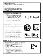
If the paddle must be trimmed, measure the 
paddle from the center of large hole (A) to the 
length required. Using non-serrated tin snips, 
trim the end (B) on a curve just like the paddle 
was originally cut.

A

B

Required
Length

STEP 1 - Paddle Sizing

1

" (25mm)


2

" (51mm)


3

" (76mm)


6

" (152mm)


Determine the correct paddle length for your installation from the
chart below.

NOTE:

All models include 4 paddles as shown.

Pipe

Flow

No-Flow

Size NPT

Maximum

Maximum

in. (mm)

Adjustment

Adjustment

2

(50)

118.5

99.5

3

(80)

278.0

227.0

4

(100)

442.0

391.0

5

(125)

847.0

762.0

6

(150)

1440.0

1325.0

Series FS8-W “K” Factor

b.

If the flow rate in the pipe exceeds the 
maximum adjustment on the Flow Switch 
use the following formula to change the
paddle lengths.

Paddle Length = 

K

_______________

Flow Rate (GPM)

NOTE:

If trimming the paddle for a no-flow action make sure

there is enough flow to activate switch.

Pipe Size

Paddle                  Trim to Length

(Standard Length)

in.

(mm)

in.

(mm)

in.

(mm)

1

(25)

1

(25)

N/A

1 1/4

(32)

2

(25)

1 1/4

(32)

1 1/2

(40)

2

(51) 

1 1/2

(38)

2

(50)

2

(51)

1 5/8

(41)

2 1/2

(65)

3

(76)

2 1/4

(57)

3

(80)

3

(76)

2 5/8

(67)

4

(100)

6

(152) 3 

5/8

(92)

6

(150)

6

(152)

5 5/8

(143)

8+

(200+)

6

(152)

N/A

Summary of Contents for McDonnell & Miller FS8-W Series

Page 1: ...cable codes and ordinances To prevent electrical shock turn off the electrical power before making electrical connections To prevent an electrical fire or equipment damage electrical wiring insulation...

Page 2: ...65 an anticipated system switch operation rate of less than once per 2 5 minutes and any one cycle greater than 3 seconds on and 3 seconds off For applications with loads 0 5 and 38mA power factors e...

Page 3: ...1 38 398 Factory or 21 2 65 Minimum 17 9 67 8 1 20 36 12 1 45 8 81 25 149 Maximum 71 3 270 4 78 1 46 59 2 224 3 97 1 21 565 Factory or 3 80 Minimum 24 2 91 6 1 05 32 16 4 62 1 71 22 230 Maximum 89 337...

Page 4: ...nt Adjustment 2 50 118 5 99 5 3 80 278 0 227 0 4 100 442 0 391 0 5 125 847 0 762 0 6 150 1440 0 1325 0 Series FS8 W K Factor b If the flow rate in the pipe exceeds the maximum adjustment on the Flow S...

Page 5: ...irection as fluid will flow Some system conditions that require more than 5 pipe diameters are high viscosity fluid and high fluid velocity The flow switch must be installed in the pump suction piping...

Page 6: ...cution when the electrical power is connected to the flow switch do not touch the terminals Make sure flow switch electrical cover is secured before turning on electric power Failure to follow this wa...

Page 7: ...used to actuate a signal alarm or other device when flow occurs connect the wire from that device to the N O contact Connect the Hot power supply wire to C terminal For No Flow Mode of Operation Fig...

Page 8: ...low switch to activate Measure flow rate and match with velocities shown in flow rate chart c Check to see if paddle moves freely Some system piping disassembly may be required 3 Flow Switch Does Not...

Reviews: