Check
Explanation/comment
Checked
Check that only necessary fittings
are used.
This helps to minimize friction losses.
Do not connect the piping to the
pump until:
•
The grout for the baseplate or
sub-base becomes hard.
•
The grout for the pit cover be-
comes hard.
•
The hold-down bolts for the
pump and the driver are tight-
ened.
—
Make sure that all the piping joints
and fittings are airtight.
This prevents air from entering the piping system or leaks
that occur during operation.
If the pump handles corrosive fluids,
make sure that the piping allows
you to flush out the liquid before
you remove the pump.
—
This helps to prevent misalignment due to linear expansion
of the piping.
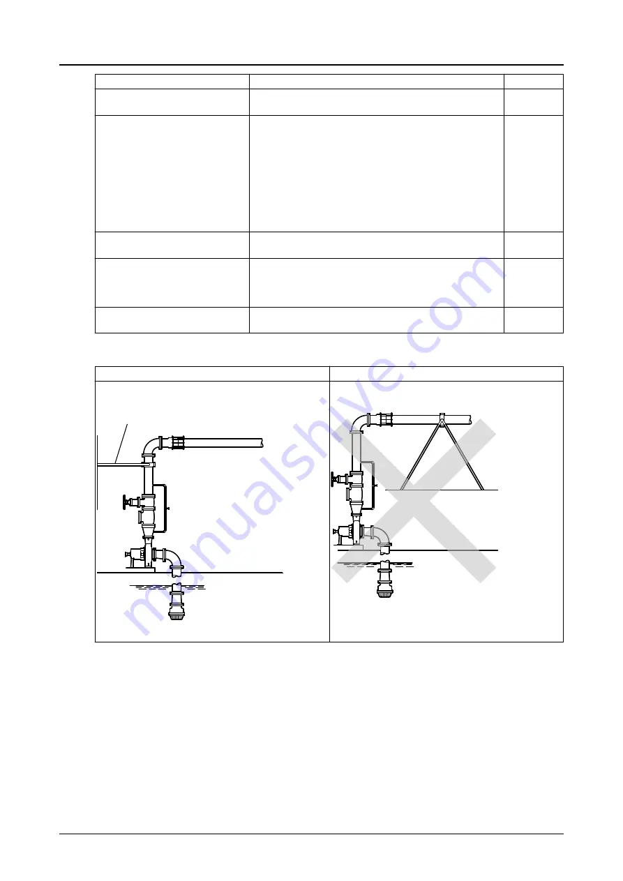
Example: Installation for expansion
Correct
Incorrect
This illustration shows a correct installation for expan-
sion:
1
1.
Expansion loop/joint
This illustration shows an incorrect installation for ex-
pansion:
4.6.2 Permitted nozzle loads and torques at the pump nozzles
Designing suction and discharge piping
The suction and discharge piping must be designed so that a minimum of forces affect the pump. Do
not exceed the force and torque values as shown in the following table. The values are valid for when
the pump is operating or when it is idle.
About the data in the table
The data in the following table has the following characteristics:
•
The data complies with the Europump Recommendation for pumps according to ISO 5199.
•
The data is only valid for static piping loads.
4.6 Piping checklists
Model IC, ICI, ICH, ICIH Installation, Operation, and Maintenance Manual
37


