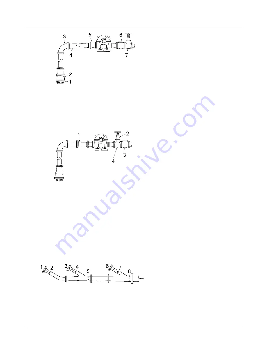
1. Strainer
5. Eccentric reducer
2. Foot valve (if used)
6. Check valve
3. Long radius elbow
7. Gate valve
4. Suction pipe slopes upwards from source of sup-
ply
Figure 25: Correct Piping
1. Air pocket because eccentric reducer is not used and because suction pipe does not slope gradually up-
ward from supply
2. Gate vale
3. Check valve
4. Gate valve should not be between check valve and pump
Figure 26: Incorrect Piping
4.
A centrifugal pump should never be throttled on the suction side.
5.
Suction strainers, when used, should have a net "free area" of at least three times the suction
pipe area.
6.
Separate suction lines should be used when more than one pump is operating from the same
source of supply. If it is not possible to have separate lines, see recommended piping arrange-
ment shown in the image below.
1. Pump
5. Area = "A" + "B" (min)
2. Area "A"
6. Pump
3. Pump
7. Area "C"
4. Area "B"
8. Area = "A" + "B" + "C" (min)
Figure 27: Recommended Piping Arrangement (when separate suction lines are not possible)
4.7 General Suction Piping
26
3175 Installation, Operation and Maintenance Instructions


