(
8
)
(
9
)
●
●
Protective resistor should be mounted to suppress the output to be
25mA or less, otherwise the driver card's integral transistor may be
damaged.
●
●
100
Ω
resistor is built-in the driver card's output section for motor pulse
signal.
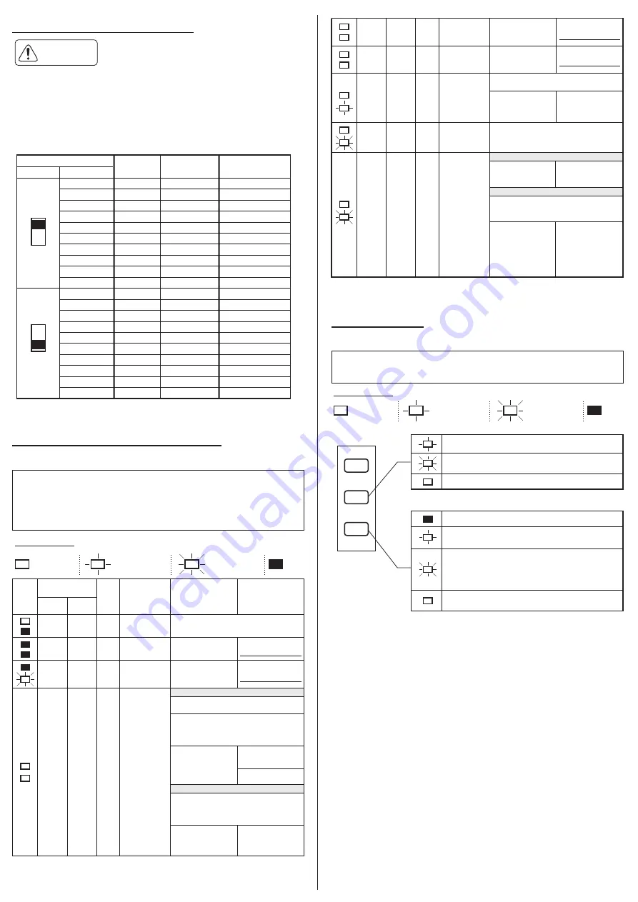
8 Error Status, Reset and History
・
MDR's motor pulse signal is discharged from CN2-5.
・
2 pulses/motor rotation, NPN open collector output.
7 Motor Pulse Signal Output
8-1 Error History
Caution
see
5 Operation Instructions
see
5 Operation Instructions
see
5 Operation Instructions
Internal speed variation
SW1-5
SW5
Frequency
(Hz)
Motor speed
(rpm)
Analog voltage
input
9
155
4638
9.6~9.9
8
152
4556
9.1~9.4
7
145
4349
8.6~8.9
6
138
4141
8.1~8.4
5
131
3934
7.6~7.9
4
124
3727
7.1~7.4
3
110
3313
6.6~6.9
2
104
3106
6.1~6.4
1
97
2899
5.6~5.9
0
90
2692
5.1~5.4
9
83
2485
4.6~4.9
8
76
2278
4.1~4.4
7
69
2071
3.6~3.9
6
62
1864
3.1~3.4
5
55
1657
2.6~2.9
4
48
1450
2.1~2.4
3
41
1242
1.6~1.9
2
35
1035
1.1~1.4
1
28
828
0.6~0.9
0
21
621
0.1~0.4
O N
O F F
Speed dev/-3%
・
When error arises, the error can be identified either by LED 1 (green) and LED 2 (red),
or by the error signal discharged from CN2-4.
・
To reset the error status, first remove the cause of error, and then switch the
direction signal at CN2-2.
・
To restart the MDR, first remove the cause of error, and then re-inject run
signal at CN2-1.
・
Please
have 100ms or more intervals between each switch for ON
→
OFF
→
ON /
OFF
→
ON
→
OFF / RUN
→
STOP
→
RUN to release error signal or restart MDR.
LED indication
CN2-4 (Error signal)
Symptom/Causes
Reset
the error signal
Restart
the MDR
MDR
SW1-4
OFF
SW1-4
ON
Open
Discharge
n.a.
n.a.
Normal operation
Open
Open
Stop
Discharge
Open
Stop
Supply 24VDC
power
No power
Discharge
Open
Stop
PCB damaged
Thermister
reacted
(Thermister error)
Shut off the power
then replace the
driver card
:
Illuminates
:
off
:
blinks at 1Hz
:
blinks at 6Hz
Discharge
Open
Stop
Connector
unplugged
Shut off the power and
replug in the connector
properly
LED 1
(green)
LED 2
(red)
Automatic recovery setting
MDR restarts immediately 1 minute after thermister
recovery from cooling off
MDR restarts by injecting RUN signal followed by
STOP signal to CN2-1 to reset the error signal then
inject RUN signal to CN2-1 to restart, 1 minute after
thermister recovery
MDR restarts by injecting RUN signal followed by
STOP signal to CN2-1 to reset the error signal then
inject RUN signal to CN2-1 to restart, 1 minute after
thermister recovery
Inject signal
RUN-STOP-RUN order to
CN2-1
Inject signal
RUN-STOP-RUN order to
CN2-1
Restarts automatically
in a minute
After thermister recovery,
inject signal ON-OFF-ON
or OFF-ON-OFF order to
CN2-2
After thermister recovery,
inject signal ON-OFF-ON
or OFF-ON-OFF order to
CN2-2
Shut off the power then
replace the MDR
Inject signal
ON-OFF-ON or
OFF-ON-OFF order to
CN2-2
Inject signal
RUN-STOP-RUN order
to CN2-1 to restart
Discharge
Open
Stop
Motor cable
disconnection
Motor stall for
4 seconds
(Stall error)
Discharge
Open
Stop
Inject signal RUN-STOP-RUN order to CN2-1 to
reset the error and to restart
Manual recovery setting
Automatic recovery setting
Manual recovery setting
Secure the stable
supply voltage 18V
or over
Restarts immediately
First secure the
stable supply
voltage 18V or over,
then inject signal
ON-OFF-ON or
OFF-ON-OFF order
to CN2-2
Inject signal
RUN-STOP-RUN
order
to CN2-1 to restart
Overload
operation
Supply voltage
less than 18VDC
(under voltage
error)
Discharge
Open
Stop
Open
Discharge
Run
*
Error can also be reset by shutting off the power 2 seconds or over.
Remove the causes of overload.
First secure the stable supply voltage 18V
or over, then inject signal RUN-STOP-RUN
order to CN2-1 for error reset and restart
・
LED of error history will not illuminate during normal operational condition, but
when motor stops with next error.
・
Please see section 8-2 for other type of error.
green
LED1
red
LED2
orange
LED3
Motor stall error / under voltage error / thermister error
Shows the error history since the card is powered. See the
below chart.
stall error
under voltage error
thermister error
Error occurred at first time
Error occurred at second time
(same error as the first one)
Error occurred at second time
(different error from the first one)
Error occurred at third time
(same error as the first or second one)
Error occurred at third time
(same error in series)
LED indication
:
Illuminates
:
off
:
blinks at 1Hz
:
blinks at 6Hz
If thermister, motor stall or under voltage error arises while the MDR is running,
the error status and frequency of error occurrence are identified by LED 2 and LED 3.
see
5 Operation Instructions


