Itm Trademaster WE-350DSA User Manual Download Page 8

- 7 - 

If the tension is set properly, but the microswitch (B) 
does not contact or trigger properly, make this 
adjustment. 
- Loosen the setscrews (D). 
- Push the microswitch (B) towards the touch plate (C).   

Make sure that the plunger is pressed properly. 

- Tighten down the setscrews (D) to secure the 

microswitch (B) in place. 

 
5.2 Adjusting the blade guide 


- Disconnect the machine from the power source. 
- Loosen hex screw (L) on the guide bar clamp. 
- Hold the handle (M) and slide blade guide bar so that 

the blade guide is as close as possible to the material 
without interfering with the cut. 

-

  Tighten hex screw (L). 

-

  Reconnect the machine to power source.   
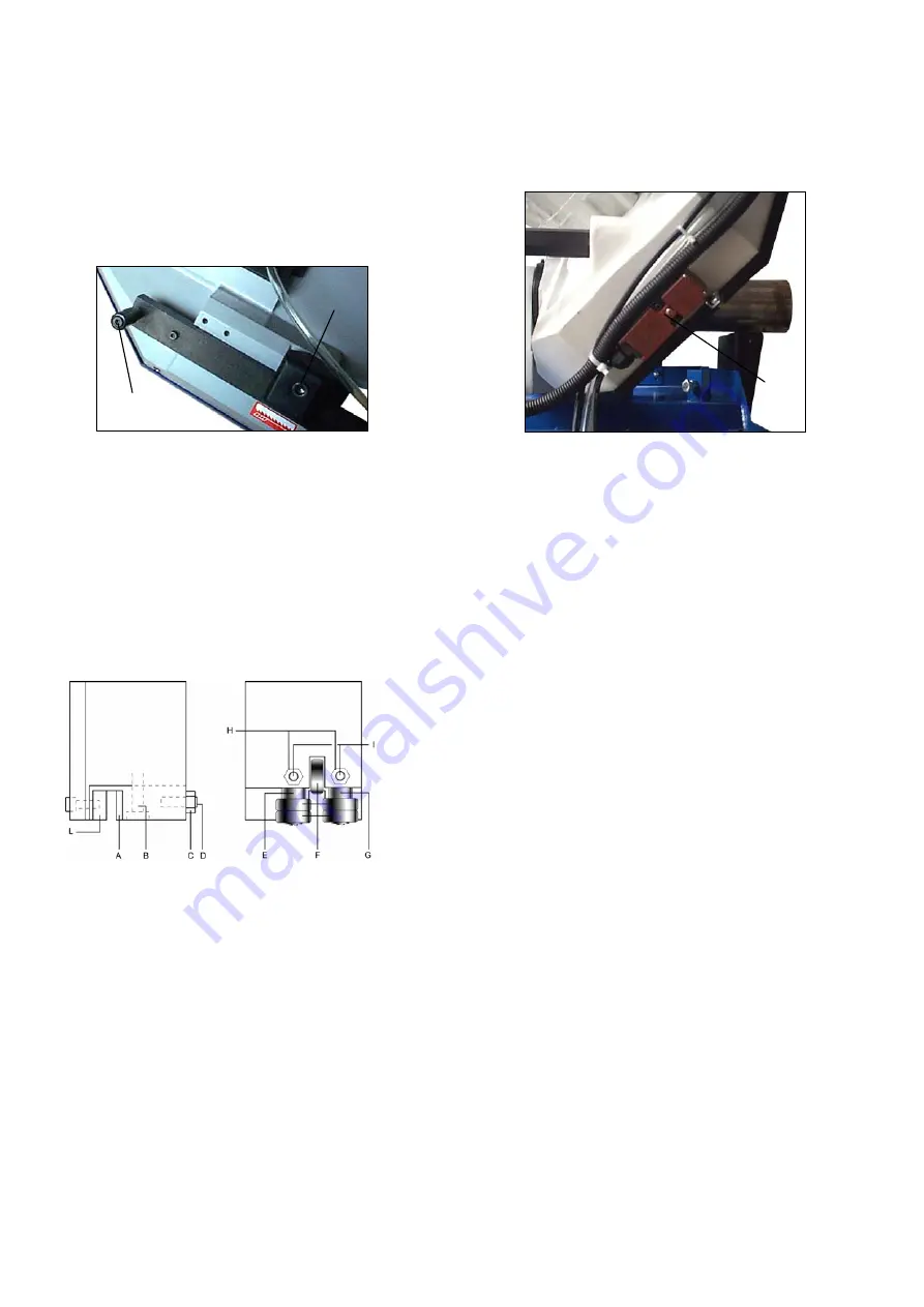
 
Blade guide blocks 

The


blade


is


guided


by


means of adjustable pads set in 

place during


inspection


as


per


the thickness of the 

blade with minimum play


as shown. 


When replacing the blade use a


0.9mm


thick


blade


for


which


the


blade


guides


have been pre-set.


For


of


blades of another


thickness,


the


adjustment


should


be


carried


out


as


follows: 

- Loosen


nut


(C),


screw


(B) and


loosen


dowel (D) 

widening the


passage


between


the


pads. 

- Loosen the nuts (H) and the dowels (I) and rotate the 

pins (E - G) to widen the passage between the 
bearings (F). 

- To mount the new blade: place the pad (A) on the 

blade, loosening the dowel, allow a play of 0.04 mm 
for the sliding of the toothed blade, lock the relative 
nut and screw (B), Rotate the pins (E - G) until the 
bearings rest against the blade


as


indicated


in


the


figure


and


then


secure


the


dowels


(I) and


nut


(H). 

- Make


sure


that


between


the


blade


and


the


upper


teeth of the pad


(L) this


is


at


least


0.2


- 0.3


mm


of


play;


if


necessary, loosen


the


screws


that


fasten the


blocks


and


adjust


accordingly. 

BEFORE PERFORMING THE FOLLOWING 
OPERATIONS, THE ELECTRIC POWER SUPPLY 
AND THE POWER CABLE MUST BE COMPLETELY 
DISCONNECTED. 
 
5.3 Changing the blade 


To change the blade: 
- Lift the saw arm. 
- Loosen the blade with the blade tension hand wheel, 

remove the blade-guards,


open


the


blade box cover


and


remove


the old


blade


from


the


flywheels


and


the


blade


guide


blocks. 

- Place


the


new


blade


in


between


the


blade guide


pads 

and


on


the


race


of


the


flywheels.


Check the cutting


direction


of


the


teeth. 

- Tension


the


blade.


  Check that it is seated


properly 

on the


flywheels. 

- Replace


and fasten


the


blade guards and


the


flywheel


guard. Check the safety 

interlock switch (N)


is activated otherwise the machine will not start. 

 
WARNING:


Always


use


blades


with the same 

thickness


as specified


by


this


manual to match the 

blade guide’s factory setting;


otherwise,


see


chapter


5.4 Saw frame return stroke-limiting device 

It


consists


in


a mechanical


adjustment


system,


mounted


parallel


to


the


saw


frame


rise


cylinder,


to


reduce


the


passive


phases


of the


operating


cycle. 


In


other


words


to


eliminate


the


idle


stroke that


takes


place


when


the


size


of


the


part


to


be


cut


is


much smaller


than


the


maximum


cutting


capacity.


Practically,


you


adjust


the


starting


position


of


the


blade


in


proximity


of


the


part, independently


of


its


dimensions. 

 
Operate


as


follows: 

- Slightly


open


the


flow regulation valve(K). 

- Bring


the


blade


as


near


as


10mm


from


the


work piece


with the bow up/bow down switches (C and D). 

- Loosen handle (7) to release the adjustable stop (8) 

against the limit switch (9). 

- Lock the handle (7) 
 
ATTENTION: 
- It


is


necessary


to


adjust


the


mechanical


stop


(8) 

every time; bring


the


blade


near


the


workpiece


by


means of


bow switch


(D) and


then


start


the


automatic


cutting


cycle (F) which


will


begin


operation from


this


position


of


the


blade. 

Summary of Contents for Trademaster WE-350DSA

Page 1: ......

Page 2: ...JUSTING YOUR MACHINE 5 1 Blade tension assembly 7 5 2 Adjusting the blade guide 7 5 3 Changing the blade 7 5 4 Saw frame return stroke limiting device 7 Chapter 6 ROUTINE AND SPECIAL MAINTENANCE 6 1 D...

Page 3: ...n as possible All internal operations maintenance or repairs must be performed in a well lit area or where there is sufficient light from extra sources so as to avoid the risk of even slight accidents...

Page 4: ...over the machine 2 7 Dismantling due to deterioration and or obsolescence General rules If the machine is to be permanently demolished and or scrapped divide the material to be disposed of according t...

Page 5: ...ator light 16 Foot pad s emergency button indicator light 17 Foot pad operation indicator light 3 3 Vice adjustment Clamping the Work Piece Place work piece between the jaws Use the hand wheel to clos...

Page 6: ...flow control fails to activate then switch C D and F cannot operate Indicator light 7 will blink if any are pressed indicating that start switch G has failed to activate Check the hydraulic oil level...

Page 7: ...ght 15 indicates the hydraulic motor has overloaded 6 Indicator light 11 indicates the speed is not properly selected If the saw bow up down switches are out of order then indicator lights 2 and 3 wil...

Page 8: ...ust accordingly BEFORE PERFORMING THE FOLLOWING OPERATIONS THE ELECTRIC POWER SUPPLY AND THE POWER CABLE MUST BE COMPLETELY DISCONNECTED 5 3 Changing the blade To change the blade Lift the saw arm Loo...

Page 9: ...ting device Replace the spring by loosening the upper coupling rod and releasing it from the lower tie rod 6 ROUTINE AND SPECIAL MAINTENANCE THE MAINTENANCE JOBS ARE LISTED BELOW DIVIDED INTO DAILY WE...

Page 10: ...g the 2 set screws Use a vacuum cleaner to vacuum chips and debris from the tank Replace the drain plug Thoroughly clean the pump P and replace Fill tank with coolant to a level about 25mm below the f...

Page 11: ...ion according to practical considerations and common sense so as to achieve an optimum condition that does not require countless operations to prepare the machine when there are many variations in the...

Page 12: ...ng for the first time it is good practice to run in the tool making a series of cuts at a low advance speed 30 35 cm 2 min on material of average dimensions with respect to the cutting capacity and so...

Page 13: ...thin section bars from 1 to 3 mm ALTERNATE SET IN GROUPS Groups of cutting teeth right and left alternated by a straight tooth This set is associated with very fine teeth and it is used for extremely...

Page 14: ...13 10 WIRING DIAGRAMS...

Page 15: ...14...

Page 16: ...dition c Check the connection points of the safety limit switches at their locations on the machine for normal condition refer to the wire diagram No WT M3 C 01 connection wire No 4 5 6 7 8 19 and 20...

Page 17: ...ers and see if both are properly located and closed b Check the limit switches for normal condition Check the connection for wire No 61 and 68 10 Motor M1 M2 Over loaded indicator light blinking a Che...

Page 18: ...heck for clogging of coolant drain holes on the blade guide blocks and that flow is plentiful in order to facilitate the removal of chips from the blade Material surfaces can be oxidized or covered wi...

Page 19: ...lf or have hardened areas or inclusions inside the section due to productive agents used such as casting sand welding wastes etc Avoid cutting these materials or perform cutting with extreme care clea...

Page 20: ...ainst the support due to deformed or poorly welded bands tapered causing cracks and swelling of the back contour Check level of liquid in the tank Increase the flow of lubricating refrigerant checking...

Page 21: ...quality blade Worn out blade or with chipped and or broken teeth Wrong tooth pitch Blade guide block too far from material to be cut Insufficient lubricating coolant or wrong emulsion Decrease advance...

Page 22: ...M10 1 23 1 Hose 1 x45cm 1 65 Shaft Nut 1 24A Coolant and Chip Tray 1 65 1 Oil Seal 1 24 1 Plate 4 65 3 Disk 1 24 2 Hex Cap Bolt M10x20 4 65 4 Spring Washer M8 4 24 3 Nut M10 4 65 5 Hex Socket Cap Scr...

Page 23: ...Hex Socket Cap Screw M12x20 2 117 Hand Wheel 1 174A Limit Switch Plate 1 117 1 Spring Washer M6 1 175 Spring Washer M8 4 117 2 Hex Socket Cap Screw M6x25 1 176 Nut M8 4 117 3 Bushing 1 177 Spring Was...

Page 24: ...olt M6x12 2 223 Handle Wheel 1 285 Washer M6 2 223 1 Thrust Bearing 51103 1 326A Flow Control 1 223 2 Blade Tension Gauge 1 327A Hose 2 5 meters 1 223 3 Plate 1 328A Hose 2 0 meters 1 224 Special Spri...

Page 25: ...24...

Page 26: ...25...

Page 27: ...26...

Page 28: ...5 6 2 7 0 2 2 7 3 2 2 7 4 2 2 7 2 1 2 2 7 2 2 7 6 4 2 7 5 2 6 6 8 2 6 5 8 2 6 4 2 2 6 5 1 2 2 6 9 2 2 5 9 2 2 6 1 2 6 0 2 6 8 2 2 6 7 2 2 4 9 1 2 6 2 2 2 6 3 2 2 8 0 2 7 9 2 2 5 0 4 2 4 9 2 5 1 2 2 8...

Page 29: ...28 327A Semi Auto and Vise Hydraulic System 332A 335A 333A 171 338A 339A Z 334A 337A 1 336A 337A 341A 340A 159 330A 326A 114 c p 328A 332A 329A 331A ADJ Pressure 15 30kg cm Vise pressure ADJ Z _...

Reviews: