Toll Free: +1 (866) 624-8309
www.itl-llc.com
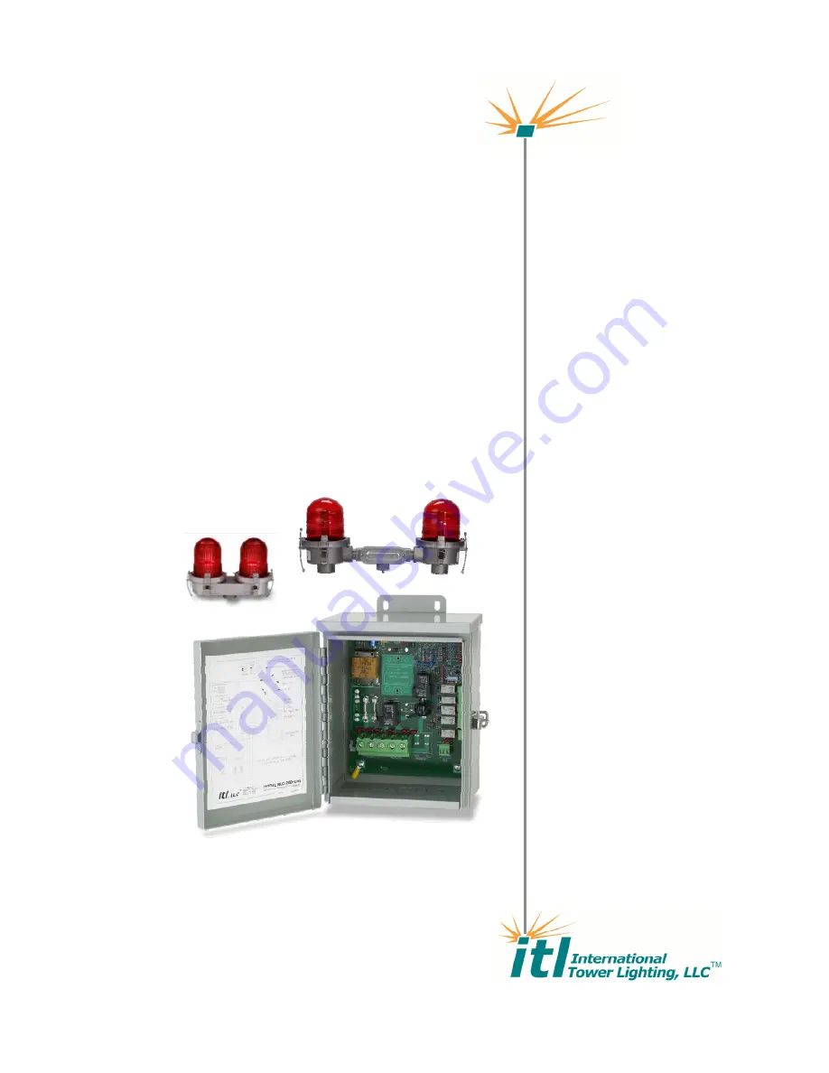
Installation
and
Operation
Manual
RLC-0200-UNI
Universal LED & Incandescent A-0 Controller
Page 1: ...Toll Free 1 866 624 8309 www itl llc com Installation and Operation Manual RLC 0200 UNI Universal LED Incandescent A 0Controller...
Page 2: ...y period please contact ITL LLC in order to obtain a Return Authorization Number RMA In no event shall ITL LLC s liability exceed the price paid for the product from direct indirect special incidental...
Page 3: ...serious injury and or death Do not attempt to service this equipment with line power applied Do not rely on interlock switches to remove lethal voltages from the system Measure for voltages using a v...
Page 4: ...ent 6 Obstruction Lights 6 Mechanical 6 Electrical 6 Installation 7 Unpacking your RLC 200 Controller 7 Quick Installation Guide 7 RLC 200 Controller Mounting 8 Electrical Connections 9 Connector Desc...
Page 5: ...rsonnel Please take the time to read and familiarize yourself with this manual It contains the information necessary to install test and troubleshoot the RLC 200 Product Description The RLC 200 is cap...
Page 6: ...struction Lights Side Lights Up to Five Incandescent 116W 120 Vac or 100W 230 Vac Up to Five LED ITL MKR LTE1 000 MKR LTE1 0IR or Other 7W LED markers lights Mechanical Dimension Height 12 00 305mm Wi...
Page 7: ...and report any potential shipping damage to the carrier Quick Installation Guide The quick start guide shows how to install the RLC 200 controller Remove RLC 200 controller from packaging material Mo...
Page 8: ...RLC 200 DOC RLC200 MNL Rev8 doc 6 13 2017 Copyright 1999 2017 ITL LLC Page 8 of 15 RLC 200 Controller Mounting...
Page 9: ...P2 and P4 located at the bottom of the controller Connections for alarm relays are made on P5 and P6 located on the right side of the controller Typical connections for a 120VAC system are shown belo...
Page 10: ...or Descriptions Connector Terminals Function P1 L1 N Input Power Line Voltage Input Power Neutral P2 PRI N SEC Primary Obstruction Lights Power Supply Neutral Secondary backup Obstruction Lights P4 BL...
Page 11: ...Operation Setup and operation of the RLC 200 is performed using the Configuration Jumpers Configuration DIP Switches the Marker Alarm Setting dial and the Manual Mode Select Switch Configuration Jump...
Page 12: ...tion Function 1 Transfer Enable ON Transfer Enable OFF Transfer Disable 2 Transfer Alarm ON K7 is Transfer Alarm OFF K7 is Mode Relay 3 Not Used 4 Not Used 5 Not Used 6 Marker Type See Marker Configur...
Page 13: ...l mode This switch should be left in the AUTO position for normal operation In the AUTO position the operating mode is determined by the photoelectric cell Indicator Lights Indicator Lights Descriptio...
Page 14: ...ruction Light Incandescent MKR LTE1 000 L 810 L Obstruction Light LED MKR LTE1 0IR L 810 L Obstruction Light LED with Infrared MKR LTE2 000 L 810 L Double Obstruction Light LED MKR LTE2 0IR L 810 L Do...
Page 15: ...ning equipment for repair and obtain a Return Material Authorization RMA number Revision Description of Change Date Preparer Approval 8 Updated Spare Parts Replacement Parts List Updated Suppression d...