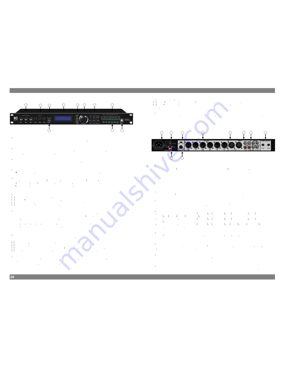
Front Panel
IV. Front Panel’s Functions Introduction
1
2
3
4
5
6
7
9
8
10
11
05
05
V. Rear Panel’s Functions Introduction
05
05
1
Wired microphone socket
Have three groups microphone socket with switch on the front panel the priority and gain is higher
than Rear Panel's .
2
Microphone volume knob
There are 3 groups to Control each microphone volume
Mic1 and Mic4 for a group
Mic2 and Mic5
for a group
and Mic3 is a single group
3
Infrared receiving window
Equiped with remote control operation throuth remote controller
the detail please refer the part of
“Remote control Function introduction”.
4
LCD display
144 32
LCD Screen
display operation interface and information of each menu
5
Input function editing keys
(1) MIC
2) EFFECT
3) MUSIC
Short touch press
Mute Unmute Switch
when in Mute the key's light is in red
Long touch press
access Input editing function interface detail please refer the part of “Input
Controlling function Setup”
.
6
Encoder
1
Clockwise
Parameters increase
and moves right or move down the menu
2
Counter clockwise: Parameters decrease
and moves left or move up menu
3
One-touch press
“Enter” key is for access or confirmation
4
Continuous press
Special confirmation
7
Function selection / Auxiliary editing keys
(1) EQ
;
(2) DELAY
;
(3) POLARITY
(4) GAIN
;
(5) LIMITER
;
(6) X OVER
(7) ESC
(8) SYSTEM
(9) PROGRAM
And (1)
(2)
(3)
(4)
(5)
(6) are input
output Function select
keys
(8)
(9) are system Function select keys
(7) is globalfunction key
8
LED Indicator
6 Bands LED Digital Level Meter showing status of input output and Editing(5.1CHs 6 group,3.1CHs
4 group)
1 CLIP display
when signal is in THD
the light is in red
2 Limit display
when signal over the value you set up
the light is in yellow.
3 3 Bands LED Level display the range from
24dBto 0dB
the light is in Green
4 EDIT
When the light is in yellow
showing which Channel are being edit
9
Feedback control key
This key have 5 states
when closed the light is turn off
when from level 1 to 4 the light is in
yellow
To switch the states
just press the key
10
Output mute
Edit keys
1
Short
touch press when in Mute No mute Switch the key's light is in red
2
Long
touch press
when access Output editing function interface
the EDIT indicator light is
turn on
detail please refer the part of “Output Controlling function Setup”.
11
USB COM Port
Communicates with PC Through PC interface software
the related Parameters can be adjusted
12
Power Switch
Access input Voltage
which marked on the power converter Switch
press the Switch and it will
work normally
13
Power Select Switch
Grid voltage Correspingding Switch.
Warning: Be sure to press the AC input voltage value corresponding to the selected
input voltage stalls, or may damage the machine
14
Ground Strobe gating
Control the Turn on
Turn off communication between Chassis and Signal ground
15
Remote control
Can instead of remote control to realize the remote control functions
also can realize the unified
system control through conneting Central console
16
Audio Output
a
6 channels output
Marked as
L
left Main
R Right Main
SL
Left Surround
SR
right
Surround
C
central
SUB
Subwoofer
Standard 5 1 Channel output
b
4 channels output
Marked as
L
left Main
R Right Main
SL
Left Surround
SR
right
Surround
Standard 4 Channel output
c
4 channels output
Marked as
L
left Main
R Right Main
C
central
SUB
Subwoofer
Standard 3 1 Channel output
17
Audio Input
3 Optional Automatic Groups mic Audio Inputs
Marked as BGM
VOD
AUX have association with
Music input,VOD gain is 6dB higher than BGM, And 3dB higher than AUX.
18
Video Input
3 Video Inputs and 1 Output
And for 3 Optional Automatic Video Inputs
Marked as BGM
VOD
AUX
have association with Music input
19
Wireless microphone Input
Rear have two microphone sockets , marked as MIC4
MIC5
•C
the priority and gain is lower than Front
Panel's .
20
AC Power Input Socket
Access corresponding AC input voltage according to the Power Select Switch gear instruction
20
12
14
16
17
17
18
19
15
13
Rear Panel
Summary of Contents for TS-211
Page 1: ...KARAOK PRE AMPLIFIER TS 211...
Page 2: ......


