


9
5. OPERATION ILLUSTRATION
Local/remote
volume
control
INPUTx
priority
control
Description
:
Phantom
function
5. Description of ALARM and EMC IN
Local
volume
control
:
Turn
the
switch
corresponding
to
CH1-REMOTE
to
OFF
,
and
the
other
channels
are
the
same
.
Remote volume control: Turn the switch corresponding to CH1-REMOTE to ON, and the other
channels are the same.
INPUTx normal priority: Turn
the
switch
corresponding
to
INPUTx
Priority
to OFF.
INPUTx
high
priority
:
Turn
the
switch
corresponding
to
INPUTx
Priority
to
ON
.
When
INPUTx
is
set
to
high
priority,
the
priority
of
INPUTx
is
higher
than
that
of
LINE1
and
LINE2
.
It
means
once
the
matrix
switch
between
INPUTx
and
output
channel
CHx
is
turned
on,
the
matrix
switch
between
LINE1,
LINE2
and
output
channel
CHx
will
be
automatically
turned
off,
regardless
of
whether
the
switch
between
LINE1,
LINE2
and
CHx
is
turned
on
.
When
INPUTx
is
set
to
normal
priority,
INPUTx
and
LINEx
have
the
same
priority
.
Turn
on
the
Phantom
function
:
Turn
the
dial
switch
corresponding
to
INPUTx
Phantom
to
ON
.
Turn
off
the
Phantom
function
:
Turn
the
dial
switch
corresponding
to
INPUTx
Phantom
to
OFF
.
The
ALARM
and
EMC
IN
trigger
and
input
interfaces
are
shown
in
the
figure
above
.
For
EMC
trigger
,
you
only
need
to
input
audio
to
the
EMC
IN
interface
to
trigger
.
When
triggered
,
the
home
page
of
the
screen
interface
will
display
:
"EMC
audio
input"
.
Before using the ALARM function, you need to insert a TF card in the front panel, and put the alarm
audio file in the specified folder of the TF card. The specific folder is named
ALARM1
corresponding
folder
:
_
ALARM1 FOLDER
ALARM2
corresponding
folder
:
_
ALARM2
_
FOLDER
_
G
+
EMC IN
ALARM
G
2
1
Note
:
The
folder
must
be
placed
in
the
root
directory
of
the
TF
card
.
Each
alarm
audio
folder
can
only
contain
one
audio
file
.
If
multiple
audio
files
are
placed
,
only
one
can
be
recognized
.
When
an
alarm
is
triggered
,
the
audio
file
under
the
corresponding
file
will
be
played
cyclically
,
and
the
screen
interface
will
automatically
jump
to
the
home
page
,
and
the
alarm
information
will
be
displayed
below
.
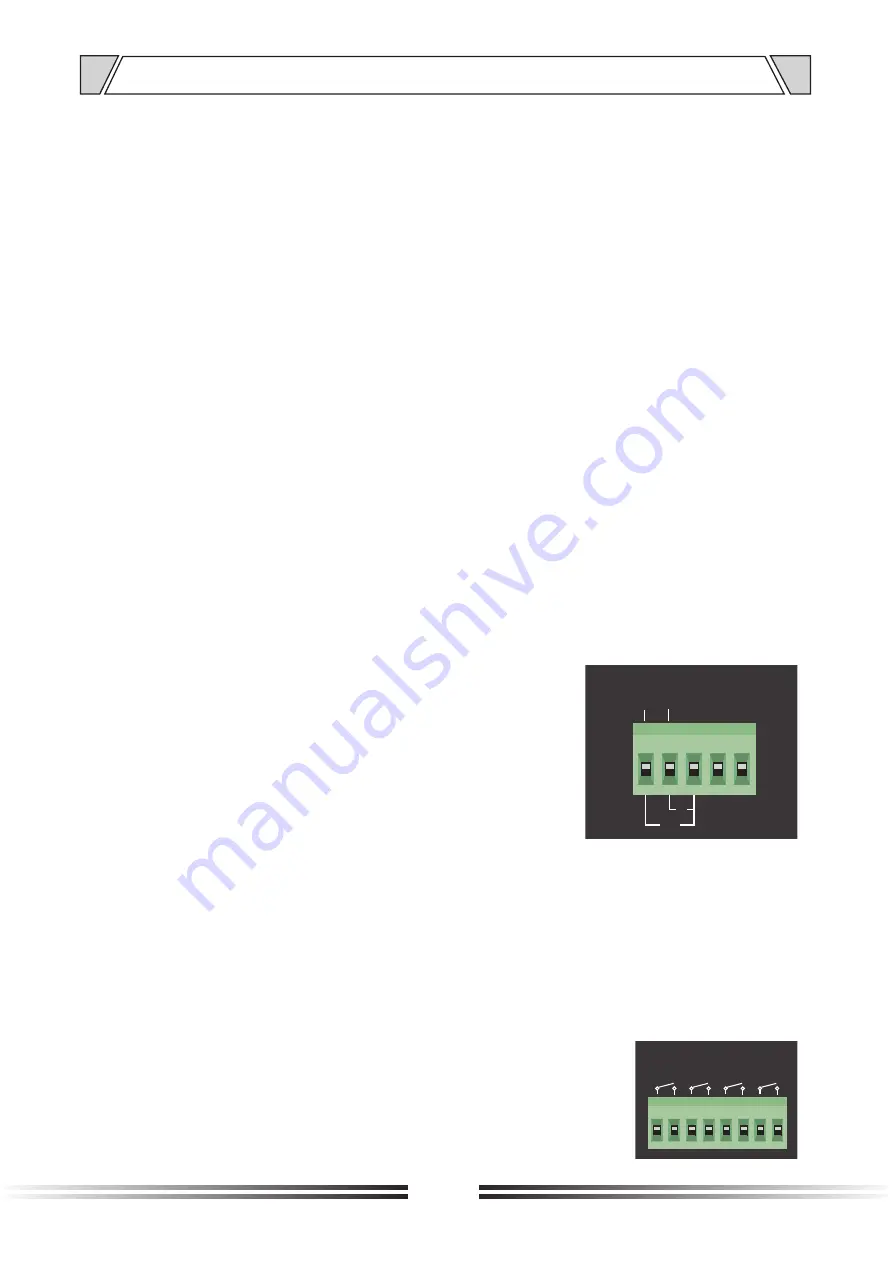
6. MUTE
description
The
MUTE
trigger
port
is
shown
in
the
figure
above
.
To
mute
a
channel
,
just
short-circuit
the
port
in
the
figure
,
but
note
that
the
corresponding
channel
will
not
be
muted
when
EMC
is
triggered
.
MUTE
CH1
CH3 CH2
CH4


